PV Module Reliability Tests: The Full List, What Each One Breaks, and What You Can Run In-House
Table of Contents
PV module reliability testing comes down to a fixed list of accelerated tests, each one designed to break a specific part of the module, and each one read out through the same four measurements: IV power, electroluminescence, visual inspection and insulation resistance. IEC 61215 sets the qualification baseline; customer specifications and third-party programmes such as PVEL add severity on top of it. Below is the full test list, what each test is actually trying to destroy, and which side of the module — cell or laminate — usually fails first.
Read This First: the Abbreviations Are Not Standard
Before the tables, one warning that saves a lot of confusion in procurement meetings. The industry shorthand for these tests is used inconsistently, and some of it contradicts the standard it claims to reference.
IEC 61215-2 numbers its procedures as MQT items. The relevant ones are:
| IEC 61215-2 procedure | MQT number |
|---|---|
| Hot-spot endurance test | MQT 09 |
| Thermal cycling test | MQT 11 |
| Humidity-freeze test | MQT 12 |
| Damp-heat test | MQT 13 |
| Wet leakage current test | MQT 15 |
| Mechanical load test | MQT 16 |
| Hail test | MQT 17 |
| Bypass diode thermal test | MQT 18 |
Now compare that with how the same tests are commonly written in quotation packages and internal reports:
- HF is routinely used to mean hail. In IEC 61215, HF is the humidity-freeze cycle (MQT 12). Hail impact is MQT 17 and has no HF designation.
- DH is sometimes used to mean damp heat with a freeze step. Damp heat is MQT 13; the freeze step is the separate humidity-freeze test (MQT 12).
- HS is used for both hot spot and humidity soak, and humidity soak is not an IEC 61215 procedure name at all — the standard's damp-heat procedure is DH.
None of this is pedantry. If your test specification says HF and your supplier reads it as humidity-freeze while your customer reads it as hail, you will discover the difference at the qualification report, not at the quotation. Write the MQT number, not the abbreviation.
The Qualification Tests
| Test | What it simulates | Typical severity | IEC reference |
|---|---|---|---|
| Thermal cycling (TC) | Day-night and seasonal temperature swings | −40 °C to +85 °C; 200 cycles for qualification, 50 for screening | MQT 11 |
| Humidity-freeze (HF) | Freeze-thaw with moisture present | Cyclic, with a freeze phase after damp exposure | MQT 12 |
| Damp heat (DH) | Hot, humid coastal or tropical climate | 85 °C / 85 %RH for 1,000 h; customers often extend to 2,000 h | MQT 13 |
| Hot-spot endurance | Partial shading forcing a cell into reverse bias | One cell partially shaded at 1 sun for 5 h | MQT 09 |
| Hail impact | Mechanical impact from ice | Specified ice ball mass and velocity at defined impact points | MQT 17 |
| Mechanical load | Wind and snow pressure on the laminate | Uniform load, typically 2,400 Pa or higher, front and rear | MQT 16 |
| UV preconditioning | Years of ultraviolet exposure | Defined UV dose, front and rear for bifacial | IEC 61215-2 |
| Wet leakage current | Insulation integrity in wet conditions | Insulation resistance measured with the module wetted | MQT 15 |
| Bypass diode thermal | Diode heating under sustained bypass current | Forced current through the diode with temperature monitoring | MQT 18 |
Two things about this list are worth stating plainly. TC50 is a screening test for internal development; TC200 is what qualification requires. And DH1000 is the qualification baseline — a customer asking for DH2000 is asking for double the exposure, which is a real engineering difference and not a paperwork exercise.
The Extended and Market-Specific Tests
These are not IEC 61215 qualification requirements. They come from third-party programmes, customer specifications or the destination market, and they are where a lot of tender requirements actually live.
| Test | Why it is requested | Note |
|---|---|---|
| PID, extended duration | High-voltage system stress, sodium ion migration | Third-party programmes commonly run 192 h at 85 °C / 85 %RH with −1,000 V or −1,500 V applied, against the standard's shorter duration. Frequently demanded in utility-scale tenders |
| Damp heat, extended | Double the qualification exposure | 1,000 h is the baseline; 2,000 h is a customer extension |
| Salt mist corrosion | Coastal and offshore installations | IEC 61701 — attacks metallisation, frames and interconnection |
| Ammonia corrosion | Agricultural and livestock-adjacent sites | IEC 62716 — attacks metallisation, encapsulant and frame |
| Sand and dust | Desert and arid sites | Abrasion of the anti-reflective coating and glass, plus accumulation |
| Snow load | Sustained static load, not cyclic | Long-duration static deflection rather than repeated cycling |
| Immersion | Flood-risk and floating applications | Complete sealing failure is the failure mode |
| Impulse / surge | Lightning-induced transients | Junction box protection and insulation spacing |
What Actually Fails: Cell Side versus Module Side
This is the part that matters most in production, because it tells you whether a failure points at your cell supplier or at your own lamination and assembly line. The table below consolidates the failure causes reported in a Chinese industry compilation of these tests, reorganised by test.
| Test | Cell-side causes | Module-side causes |
|---|---|---|
| Light-induced degradation (LID) | Boron-oxygen complexes activated by light in boron-doped silicon; high oxygen content; sintering and annealing off-window; metallic contamination in the wafer | Lamination and curing temperatures altering the cell's annealed state; an unfavourable hydrogen environment inside the laminate accelerating defect activation |
| LeTID, late-stage degradation | Hydrogen distribution inside the wafer; sintering and annealing parameter drift; carbon and metallic contamination | Encapsulant decomposition supplying additional hydrogen; sustained high operating temperature accelerating the reaction |
| PID | Poorly densified or pinhole-containing passivation layers; incomplete edge isolation causing edge leakage; insufficient passivation insulation resistance | Sodium release from soda-lime glass; low encapsulant volume resistivity; edge seal failure allowing moisture ingress; inadequate frame grounding |
| Damp heat | Weak edge passivation; corrosion-prone metallisation; inadequate edge insulation | Poor backsheet moisture barrier; edge sealant failure; encapsulant hydrolysis producing acetic acid; voids left by incomplete lamination |
| Hot spot | High reverse leakage current; contamination or localised low-current regions; broken fingers and microcracks creating current mismatch | Current mismatch within the string; wrong bypass diode selection or a cold solder joint; sustained external shading or soiling |
| Microcracks (found by EL) | Thin wafer brittleness; residual stress from printing and sintering; handling damage during cutting, sorting and transport | Uneven lamination pressure; tensile stress from ribbon soldering; stress during framing, handling and mechanical load; cool-down stress after lamination |
| UV degradation | Anti-reflective coating with insufficient UV stability; refractive index shift raising optical absorption | Insufficient UV stabiliser in encapsulant or backsheet; yellowing reducing transmission; backsheet cracking admitting moisture |
| Thermal cycling | Residual stress in the cell; thermal expansion mismatch between metallisation and silicon | Expansion mismatch across ribbon, cell, glass and encapsulant; cold solder joints concentrating stress; residual lamination stress |
| Hail impact | Thin wafer with low impact strength; microcracks already present on arrival; residual process stress | Insufficient glass thickness or poor tempering; encapsulant too hard or too thin to absorb energy; weak frame support; unsuitable cell spacing |
| Mechanical load | Pre-existing microcracks; low wafer strength under deflection | Inadequate frame strength or bonding; poor cell spacing design; insufficient backsheet stiffness; internal lamination stress |
| Salt mist | Silver and silver-aluminium fingers vulnerable to chloride attack; weak edge protection; low sintered paste density | Damaged frame anodising; failed frame or backsheet sealing; junction box sealing defects; ribbon coating corrosion |
| Ammonia | Metallisation and passivation degradation under ammonia plus moisture | Encapsulant and backsheet permeability; frame and material reaction; accelerated hydrolysis |
| Wet leakage and insulation | Incomplete edge isolation; insufficient edge insulation; burrs and sharp edges causing partial discharge | Insufficient or pinhole-affected insulation layers; excessive frame grounding resistance; inadequate creepage distance in the junction box |
| Peel and adhesion | Low surface energy of the cell coating giving weak encapsulant adhesion | Lamination temperature, time or pressure below target; poor glass or backsheet surface preparation; encapsulant formulation mismatch |
Read down the two columns and the split is consistent: the cell column is about material quality and thermal history; the module column is about interfaces, sealing, stress and process window. That is the practical diagnostic rule this table is really encoding.
What You Can Test In-House, and What You Cannot
Most factories treat reliability testing as something that happens at a laboratory. In practice the split is different, and knowing where the line falls changes how fast you can react to a failure.
Tests that need a chamber or a lab
Thermal cycling, humidity-freeze, damp heat, PID, salt mist, ammonia and UV preconditioning all require environmental chambers with calibrated control and long unattended run times. Nobody runs these as a daily production check.
Tests you can and should run on the line
The readout measurements — the four that every one of the tests above is judged by — are all production-capable:
- IV power and electrical performance. An A+A+A+ class simulator and IV tester gives you the power measurement that every test result is expressed against. Our XJCM-13A+ module IV tester, the OTMT-A sun simulator and the ST-TLD3A+ IV tester are built for inline or offline use at production rates.
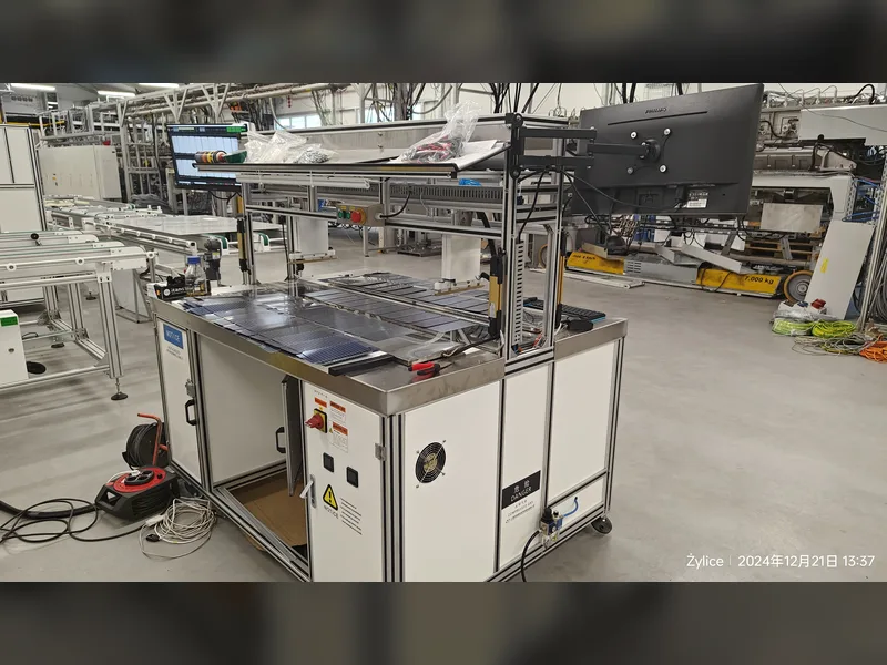
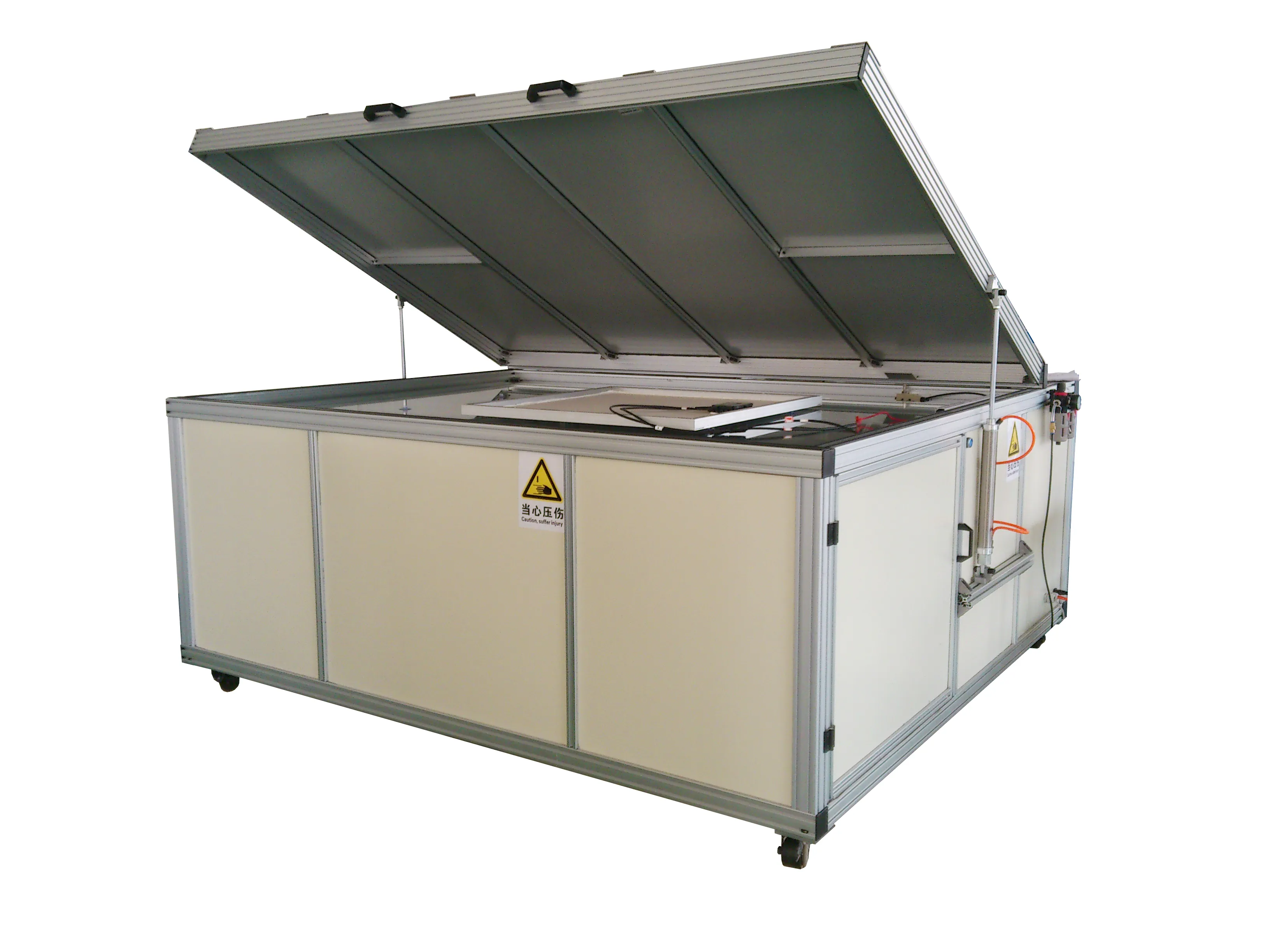
- Electroluminescence. EL is how microcracks, broken fingers, inactive areas and PID-affected cells are actually found. Inline EL and VI inspection, a standalone module EL station such as the OEL-S2400, and a handheld unit for field or receiving inspection are three different jobs. The portable EL tester is what you use to check incoming cells and returned modules without stopping the line.
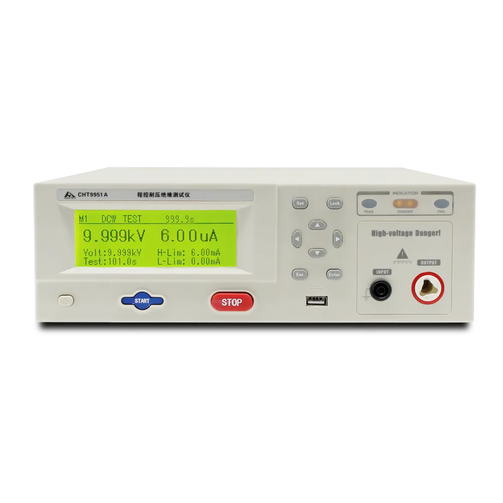
- Insulation, hipot and ground continuity. These are the safety readouts, and they are fast enough to run per module. The CHT9980A comprehensive safety tester covers hipot, insulation and ground continuity in one station; the CHT9951A and CHT9930A cover the individual functions.
- Visual inspection. Still a required readout, and still the cheapest one.
Where in-house testing actually pays back
Two situations. First, when a customer returns modules or a batch fails at the destination: having your own EL and IV capability means you can characterise the failure in hours rather than shipping samples out and waiting. Second, when you change a material — a new encapsulant, a thinner wafer, a different ribbon — a before-and-after IV and EL comparison on your own line catches the process-related failure modes (lamination voids, solder stress, handling cracks) long before a chamber test would.
What in-house testing cannot do is substitute for the chamber tests. It can tell you that something changed; it cannot tell you how the module behaves after 1,000 hours at 85 °C and 85 %RH.
How to Read a Reliability Report
Whichever test is involved, the report is only meaningful if it answers these questions:
- Which procedure and which revision? The MQT number and the standard year. IEC 61215-2 has been revised; results are not interchangeable across revisions.
- What were the four readouts before and after? IV power, EL, visual, insulation resistance. A pass on power alone can hide an EL change that predicts a field failure.
- What was the pass criterion, and who set it? The standard criterion and the customer criterion are usually different. Power degradation limits of 5 % are common but not universal.
- How many samples, from which production period? A result from three modules built in one afternoon is a sample of that afternoon.
- What was the failure, if there was one, and which side of the table did it land on? This is where the cell-versus-module split above becomes useful: it tells you who needs to act.
Frequently Asked Questions
Is IEC 61215 a reliability standard or a safety standard?
IEC 61215 is design qualification and type approval — it establishes that a design can survive the listed stresses. Safety is IEC 61730. A module needs both, and a pass in one says nothing about the other.
What is the difference between TC50 and TC200?
Only the number of cycles, but the purpose differs. TC50 is a development and screening test used to catch obvious material and solder problems quickly. TC200 is the qualification requirement under IEC 61215. Passing TC50 does not imply passing TC200.
Why do customers ask for PID at 192 hours when the standard is shorter?
Because the standard duration was set as a qualification floor, and utility-scale buyers have seen field PID failures that a floor-level test did not predict. Extended PID, usually at high voltage and 85 °C / 85 %RH, is a customer or third-party programme requirement rather than an IEC requirement.
Does LID matter for N-type modules?
Boron-oxygen LID is primarily a boron-doped P-type issue. N-type cells such as TOPCon and heterojunction are largely free of it, which is one reason the industry moved. The degradation mechanism to watch on N-type is LeTID, where hydrogen behaviour rather than boron-oxygen complexes drives the loss.
Can we qualify a module without a chamber?
No. The chamber tests are the qualification. What you can do without a chamber is detect the process-induced failure modes early, with EL and IV, and avoid shipping modules that will fail the chamber test your customer is going to run.
Where does the failure-cause content in this article come from?
The consolidated test list and the cell-side versus module-side failure causes are drawn from the Chinese industry compilation published by 新能供应链, with the standard designations corrected against the IEC 61215-2 procedure list. The severity figures and pass criteria quoted here are typical industry values, not a substitute for the standard text or your customer specification. Where the source and the standard disagreed on abbreviations, we have followed the standard and said so above.