How to Accurately Measure the IV Curve of a Solar PV Module
Product Introduction
From uncertain measurement to reliable PV module IV testing
Rated power is one of the most important electrical indicators of a photovoltaic module. But where does this number actually come from? In most professional laboratories and solar module production lines, the answer starts with the IV curve test.
The IV curve test is the core method used to evaluate solar module performance. It determines key electrical parameters such as short-circuit current, open-circuit voltage, maximum power and fill factor. These values are not just numbers printed on a label; they influence module grading, factory quality control, bankability assessment and long-term project performance prediction.
However, measuring an IV curve accurately is not as simple as placing a module under light and reading a value. Light uniformity, spectral match, module temperature, capacitance effect, contact resistance and irradiance calibration can all shift the final power result.
Basic knowledge of IV curve measurement
Before discussing how to improve measurement accuracy, it is useful to understand the basic meaning of the IV curve.
An IV curve is the current-voltage characteristic curve of a solar PV module. It shows the output current of the module under different voltage conditions. By analyzing this curve, several important parameters can be obtained.
Short-circuit current, Isc: the current value when voltage is 0. It reflects the light-generated current capability of the module.
Open-circuit voltage, Voc: the voltage value when current is 0. It reflects the electrical potential generated by the solar cells.
Maximum power point, Pmax: the point where the module delivers the highest DC output power.
To make measurement results comparable, the PV industry usually uses Standard Test Conditions, also called STC.
| Test Condition | Standard Value |
|---|---|
| Irradiance | 1000 W/m² |
| Spectrum | AM1.5G |
| Cell temperature | 25°C |
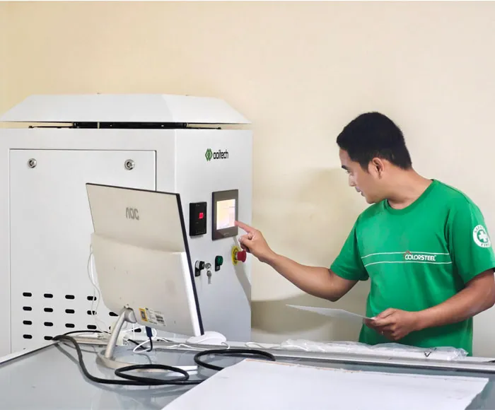
The main equipment used for IV curve measurement is the solar simulator. It creates controlled light conditions similar to sunlight and allows the tester to generate the IV curve of the module. The performance of the solar simulator directly affects the final accuracy of the measurement.
Technical Parameters
Key standards and measurement control points
Accurate IV measurement depends on both equipment performance and correct testing method. The following table summarizes the most important technical parameters and reference standards used in PV module IV testing.
| Item | Technical Requirement | Why It Matters | Related Standard or Method |
|---|---|---|---|
| Irradiance level | 1000 W/m² under STC | Directly affects Isc and Pmax | IEC 60904 series |
| Spectrum | AM1.5G reference spectrum | Reduces spectral mismatch error | IEC 60904-9, IEC 60904-7 |
| Module temperature | 25°C under STC | Power changes with temperature | IEC 60891 |
| Light uniformity | Preferably Class A+; non-uniformity less than 1% | Avoids local over-lighting or under-lighting across the module | IEC 60904-9 |
| Temporal instability | Stable light during measurement pulse or exposure period | Prevents curve distortion caused by unstable irradiance | IEC 60904-9 |
| Reference device | Calibrated WPVS cell or qualified reference module | Ensures traceability of irradiance calibration | World Photovoltaic Scale, IEC practice |
| Spectral mismatch correction | Correction factor calculated when reference device and test module differ | Improves accuracy for different cell technologies | IEC 60904-7 |
| IV curve translation | Temperature and irradiance correction when test conditions deviate from STC | Converts measured curve to standard reporting conditions | IEC 60891 |
| Contact method | Four-wire measurement recommended | Reduces voltage drop and contact resistance error | Good laboratory practice |
| Scan strategy | Slow scan, step scan, multi-flash or bidirectional scan for high-efficiency modules | Reduces capacitance and hysteresis influence | Technology-dependent test method |
Why solar simulator performance is so critical
A solar simulator is not natural sunlight. Its light intensity, spectrum, uniformity and stability must be controlled and verified. Even a small deviation may create a visible difference in the measured IV curve, especially when testing high-efficiency modules such as PERC, TOPCon, HJT or other advanced cell structures.
For production lines, this is even more important because every module is graded based on measured power. A 1% systematic error in irradiance or temperature correction can create direct commercial impact.
Technical Advantages
How to move from inaccurate testing to accurate testing
Although IV curve measurement is guided by standards, many practical issues can still reduce test accuracy. The following are the most common problems and the recommended technical solutions.
1. Light uniformity of the solar simulator
The light from the simulator should cover the entire module surface as uniformly as possible. If the irradiance is not uniform, different areas of the module receive different light intensity. This can cause current mismatch inside the module and may make the IV curve look stepped or abnormal.
Recommended solution:
Use a high-quality solar simulator with excellent light uniformity.
For precision testing, target IEC 60904-9 Class A+ uniformity, meaning non-uniformity below 1%.
Regularly map the test plane to check whether the whole module area is receiving consistent irradiance.
2. Spectrum and spectral mismatch
The spectrum of a solar simulator is never perfectly identical to the AM1.5G reference spectrum. At the same time, the spectral response of the reference device may be different from that of the module under test. This creates spectral mismatch error.
For example, a reference cell and a TOPCon module may not respond in exactly the same way to different wavelength ranges. If this difference is ignored, the measured power may be shifted.
Recommended solution:
Use a solar simulator with strong spectral match performance according to IEC 60904-9.
A lower SPC value is normally preferred.
Calculate the spectral mismatch correction factor according to IEC 60904-7.
Apply IV curve correction methods according to IEC 60891 when necessary.

3. Temperature control
Crystalline silicon PV modules are sensitive to temperature. When temperature rises by 1°C, the output power may decrease by about 0.25% to 0.5%, depending on the module technology and temperature coefficient.
This becomes especially important when using long-pulse or steady-state solar simulators. During exposure, the module temperature can rise quickly and cause measurement deviation.
Recommended solution:
Keep the test environment close to 25°C.
Use temperature sensors to monitor the module surface temperature in real time.
If the module temperature deviates from STC, apply temperature correction according to IEC 60891.
Avoid unnecessary long exposure before measurement, especially for temperature-sensitive modules.
4. Capacitance effect and hysteresis
High-efficiency modules such as PERC, TOPCon and HJT can show capacitance-related behavior during IV scanning. If the voltage scan is too fast, current and voltage may not reach a stable state at each point. The result is hysteresis, where forward and reverse scans do not fully overlap.
This directly affects measured values such as Pmax, fill factor and sometimes even Voc or Isc estimation.
Recommended solution:
Use a slower linear scan to allow the electrical response to stabilize.
Use multi-flash methods to simulate a slower scan, though this may reduce throughput.
Use step scanning, waiting at each voltage point until current stabilizes before moving to the next point.
Use forward and reverse scanning to evaluate and correct hysteresis behavior.
Technologies such as DragonBack, Dynamic IV and advanced hysteresis correction methods are examples of practical industry approaches.
5. Contact resistance
Contact resistance is a common problem in IV testing. Poor contact between the test fixture and the module terminals can cause voltage drop or unstable current measurement. This may distort the IV curve and reduce repeatability.
Recommended solution:
Use four-wire measurement to separate current-carrying and voltage-sensing paths.
Keep connectors, probes and clamps clean.
Replace worn or oxidized test contacts regularly.
Check repeatability when abnormal curves appear.
6. Irradiance calibration of the simulator
In PV module IV measurement, irradiance accuracy is one of the most important factors. STC requires testing at 1000 W/m², but the practical question is: how can we be sure that the simulator actually reaches 1000 W/m² at the test plane?
The light source of a solar simulator changes over time. Lamp aging, optical contamination and system drift may all change the actual irradiance. Therefore, regular irradiance calibration is essential.
Recommended solution:
Use a primary reference device such as a WPVS cell for calibration.
Calibrate the simulator regularly with the reference device.
Consider the relationship between irradiance at the WPVS cell position and the average irradiance over the full test plane.
If this spatial relationship is ignored, errors greater than 1% may occur.
Product Application
WPVS cell: the authoritative reference for irradiance calibration
In the photovoltaic industry, irradiance calibration is usually achieved through a calibrated reference device. The WPVS cell, short for World Photovoltaic Scale cell, is one of the most commonly used primary reference devices.
A WPVS cell is a high-precision standard solar cell used to calibrate PV module power measurement equipment. Its core function is to provide a globally consistent reference so that measurement results from different laboratories and production lines can be compared.
How a WPVS cell is calibrated
To determine whether the solar simulator irradiance is truly 1000 W/m², the WPVS cell itself must first be calibrated by an internationally recognized metrology institute.
During calibration, the institute measures the short-circuit current of the WPVS cell under standard conditions: AM1.5G spectrum and 1000 W/m² irradiance. This measured value becomes the reference value used later for solar simulator calibration.

Currently, the internationally recognized institutes capable of primary reference device calibration mainly include:
NREL, National Renewable Energy Laboratory, United States
PTB, Physikalisch-Technische Bundesanstalt, Germany
AIST, National Institute of Advanced Industrial Science and Technology, Japan
JRC, Joint Research Centre, European Union
Their calibration results are widely accepted by the international PV industry and are often considered the gold standard for PV module power measurement.
Where accurate IV testing is used
Accurate IV curve testing is essential in many PV-related scenarios:
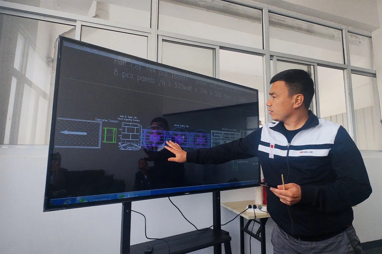
Solar module production lines: for final power measurement, sorting and labeling.
PV laboratories: for certification, research and product validation.
Quality inspection: for checking whether module performance meets purchase specifications.
New technology evaluation: for comparing PERC, TOPCon, HJT, IBC, shingled or thin-film module behavior.
Factory process control: for identifying soldering issues, mismatch, abnormal resistance or unstable module output.
In short, IV curve measurement is not only a test at the end of production. It is also a diagnostic tool that reflects material quality, cell matching, interconnection process, lamination stability and overall manufacturing control.
Contact Purchase
Practical checklist before running an IV curve test
Before starting a professional IV curve test, it is useful to confirm the following points:
The solar simulator has been recently calibrated.
The reference device is within its calibration validity period.
Light uniformity, spectrum and temporal stability meet the required class.
The module temperature is measured and recorded.
The test fixture has low and stable contact resistance.
The scan speed is suitable for the module technology being tested.
Correction methods are applied according to IEC 60891 and IEC 60904-7 when needed.
Abnormal IV curves are reviewed instead of being accepted automatically.
A reliable IV curve is the result of a full measurement system, not a single instrument reading. Good hardware, correct standards, careful calibration and stable operating procedures all matter.
Ooitech's View
As an equipment supplier working closely with solar panel production line projects, we see IV curve accuracy as a factory-level quality control issue rather than only a laboratory topic. For modern high-efficiency modules, especially TOPCon, HJT and other capacitance-sensitive technologies, the choice of simulator class, scan strategy and calibration routine can directly affect power binning and customer confidence. A well-designed module line should treat IV testing, EL inspection and process traceability as connected quality systems, not isolated stations. For manufacturers planning new capacity, investing in correct IV measurement practice early is often cheaper than correcting systematic power deviation after mass production begins.