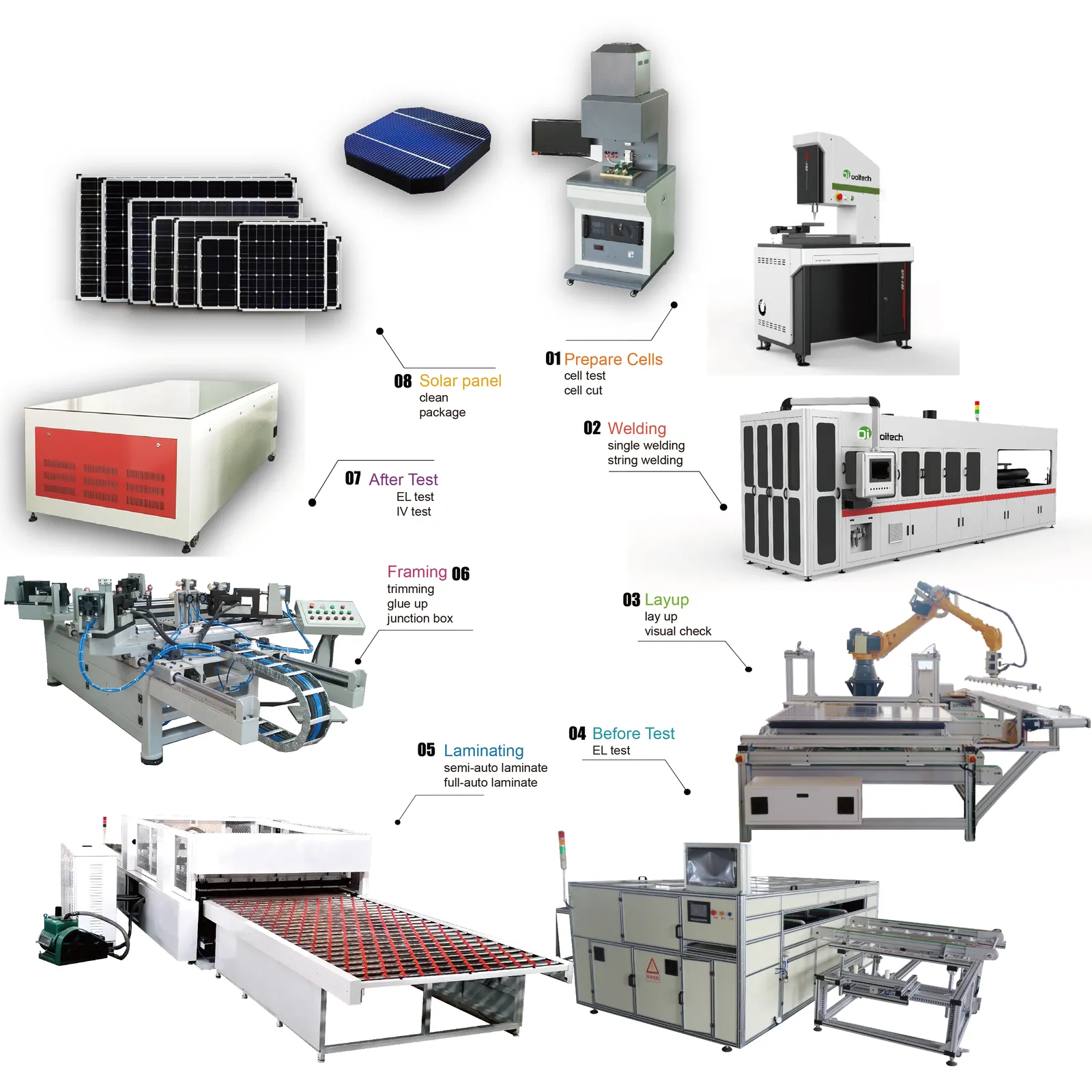
Solar Panel Production Line — Cells to Finished Modules
Table of Contents
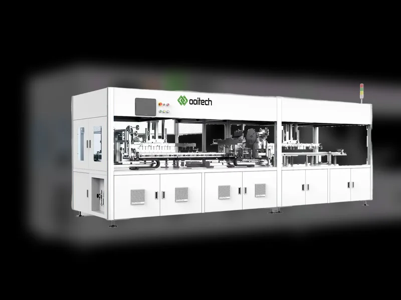
Quick answer: A solar panel production line converts fragile individual cells and rolls of material into sealed, tested modules. The sequence is fixed: cells are sorted by current, cut where half or shingled formats are used, soldered into strings by the tabber stringer, laid out with EVA and glass at the layup station, laminated under vacuum and heat, then framed, fitted with the junction box, and flashed on an IV tester before final sorting. Throughput is set by the slowest stage, not the fastest, so a line is normally specified by annual capacity and the machine count follows from it. Each station also adds a distinct failure mode, from micro-cracks at stringing to voids at lamination and delamination over time, which is why in-line inspection sits after every critical step. Electroluminescence imaging after lamination catches the defects that a power measurement alone would miss, and final sorting bins modules by measured current so that mismatched units never share a string. Typical figures for the stations involved: stringing at 1,200–6,800 cells per hour with ±0.15 mm positioning and ≤0.2% breakage on Class A cells, layup cycling under 48 seconds, lamination holding roughly 140–150°C while the encapsulant crosslinks, and IV testing classifying output against an A+ class spectrum match of 0.875–1.125.
PV Module Manufacturing · by Jerry, Ooitech
A useful way to understand a solar module factory is to ignore the machine names for a moment and watch what happens to the product.
At the beginning, there are fragile individual cells and rolls or sheets of material. In the middle, there is an electrically connected circuit trapped inside a loose stack. At the end, there is a sealed product with a serial number, measured power, inspection records, and a decision: release, rework, or reject.
That change happens in three broad transformations.
| Transformation | What enters | What must leave the stage | Main process families |
|---|---|---|---|
| Cells become a circuit | Sorted or prepared solar cells | Connected strings arranged as the intended module circuit | Cell preparation, stringing, layup, bussing, in-process inspection |
| The stack becomes a laminate | Glass, encapsulant, connected cells, and rear material | A bonded and protected laminate | Material preparation, stacking, inspection, lamination |
| The laminate becomes a released module | Laminated panel | Mechanically finished, electrically connected, tested, identified product | Trimming, framing, junction-box work, curing, EL, IV and safety testing, labeling |
This process view serves a different purpose from a machine catalogue. Readers who need a detailed equipment-by-equipment reference can use Ooitech’s article on what machines are used to make solar panels. Here, the question is how those operations depend on one another.
Cells become a controlled electrical circuit
Most module assembly plants begin with purchased photovoltaic cells. The first production decisions are already embedded in the product design: full cell or cut cell, conventional front contact or back contact, the number and position of ribbons, string length, gap, lead-out location, and final circuit arrangement.
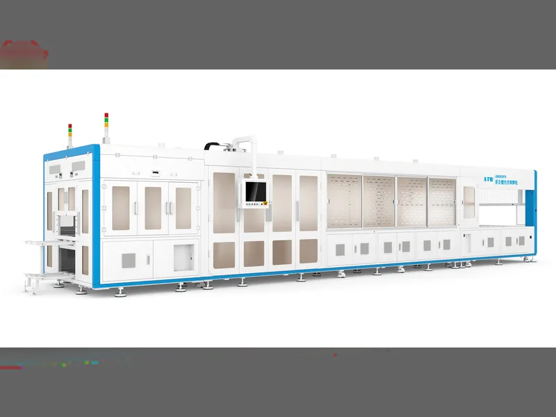
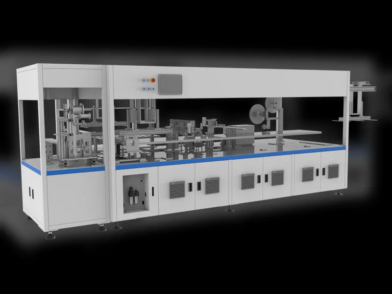
If the design uses divided cells, a laser process prepares the required pieces. The stringing process then solders conductive ribbon to the cells and connects them in series. Completed strings move to layup, where they are positioned on the prepared glass and encapsulant. Bussing joins the strings according to the module’s electrical design.
These operations are often sold as separate machine categories, but the factory experiences them as one continuous problem: build the circuit without breaking cells, overheating sensitive structures, shifting the geometry, or creating weak electrical joints.
The numbers behind that sentence are small and unforgiving. A wafer runs 130–180 μm thick, flat ribbon is commonly 0.15–0.35 mm wide, and a current-generation stringer holds positioning to ±0.15 mm while keeping breakage at or below 0.2% on Class A cells. Throughput in that same machine class spans 1,200 to 6,800 cells per hour, which is why the fastest station on paper is often not the one your laminator can absorb.
The handoffs matter. A string can pass its own visual check and still be damaged while it is lifted, turned, or placed. A correctly soldered string can become a poorly aligned module if the layup reference is wrong. A bus ribbon can be electrically connected yet positioned badly for the later junction-box process.
For this reason, cell handling, vision correction, string transport, layup accuracy, and bussing control should be engineered together. Buying each station against its own brochure specification misses the interfaces where many production losses appear.
The expensive boundary sits before lamination
Before lamination, the module can still be opened. A damaged string can be replaced. A misplaced ribbon can be corrected. Dust can be removed. Encapsulant or rear material can be repositioned.
After lamination, those same corrections become difficult, uneconomic, or impossible without sacrificing the module. That makes pre-lamination inspection more than a quality department routine. It is an economic boundary in the production flow.
A sensible gate checks two kinds of evidence.
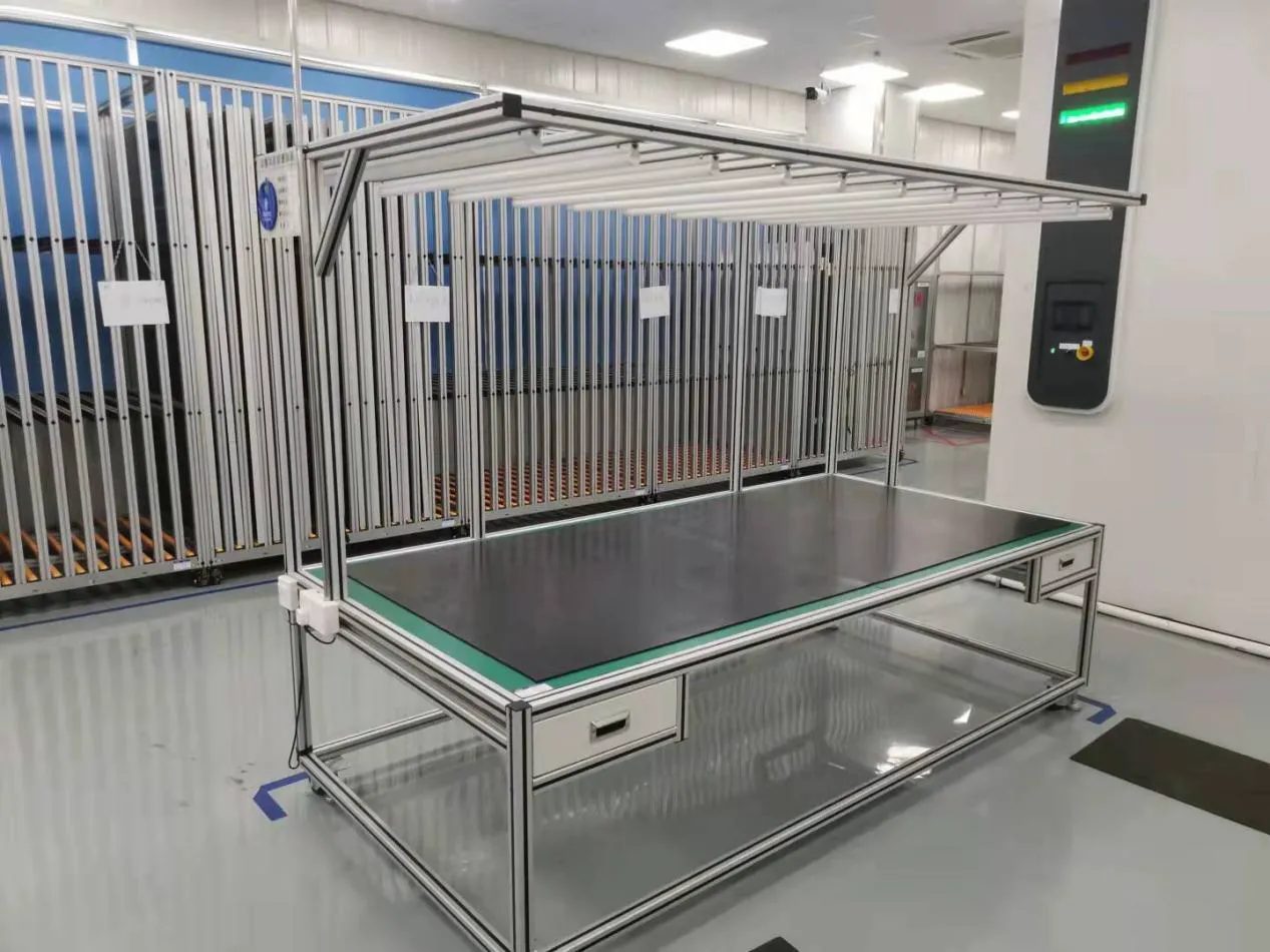
Visual inspection covers material placement, contamination, string spacing, lead-out positions, wrinkles, foreign objects, and obvious damage. EL inspection covers the electrical condition of the connected cell circuit, including defects that may not be visible under normal lighting.
The purpose is not to create another inspection report. It is to prevent avoidable defects from crossing into an irreversible process. When a line repeatedly finds the same problem at this gate, the correct response is upstream process correction—not simply adding more inspectors.
A loose stack becomes a protected laminate
The module stack normally includes front glass, encapsulant, the connected cell circuit, a second encapsulant layer, and either a polymer backsheet or rear glass. Material cutting and laying systems prepare those layers to the product dimensions. Handling equipment keeps their edges and reference points under control as the stack moves toward lamination.
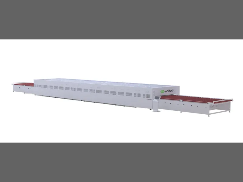
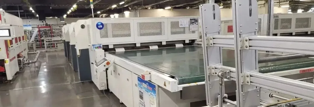
The laminator applies a controlled combination of vacuum, heat, pressure, and time. Air is removed, the encapsulant flows and cures, and the previously loose layers become one bonded structure.
This stage is governed by a recipe, not merely a temperature setting. Encapsulant chemistry, glass construction, module dimensions, material storage, evacuation behavior, heating uniformity, and cooling conditions all influence the result. A recipe suitable for one bill of materials should not be copied blindly to another.
The window is narrower than the setpoint suggests. EVA encapsulant crosslinks at roughly 140–150°C, and what the recipe actually controls is a sequence — temperature ramp, vacuum stages, applied pressure and dwell. A laminator that cannot repeat that sequence shows it as bubbles, delamination or cell shift, and none of those can be corrected once the stack is bonded.
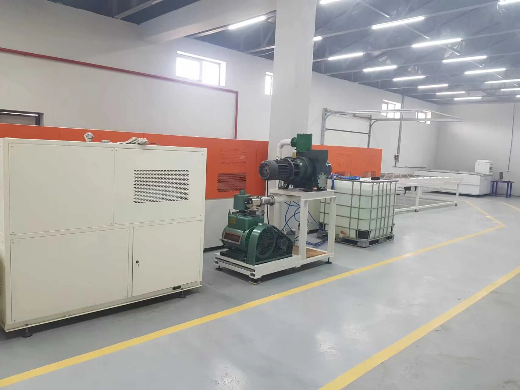
The laminator also has a strict limit: it cannot repair the stack it receives. It cannot straighten a misplaced string, remove contamination, restore a cracked cell, or correct the wrong rear material. Good lamination therefore begins well before the chamber door closes.
Factory flow around this process deserves careful planning. Unlaminated stacks are fragile and occupy space. Batch loading can create uneven arrivals and departures. Cooling and downstream handling may constrain the area even when the chamber itself appears fast enough. The useful capacity figure is the sustained flow through the complete section, not the shortest displayed recipe time.
Finishing adds function, not decoration
A laminate may already resemble a solar panel, but several functional jobs remain.
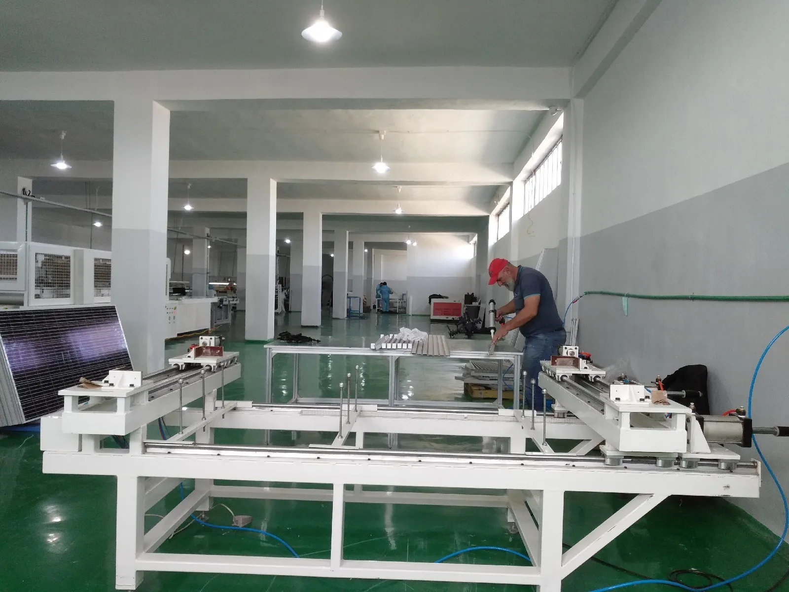
Finishing begins at the laminate perimeter, where surplus material is removed and the edges are prepared for the chosen construction. On a framed product, sealant and aluminum profiles are assembled into a square, secure load-transfer structure for packing, mounting, and field use. Frameless and glass-glass designs route this stage differently, so their handling and edge processes must be defined by the product drawing.
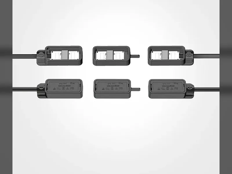
The junction box creates the external electrical connection. Lead-out ribbons must reach the correct terminals, the electrical joint must be stable, and adhesive or potting material must protect the assembly. Curing time is part of production time; moving a module too soon can disturb an otherwise acceptable installation.
These steps are sometimes treated as the easy end of the line because the solar circuit has already been built. That assumption is risky. Frame damage, poor sealing, weak terminal connections, or uncontrolled adhesive application can reject a module that passed every earlier stage.
The tolerances are worth stating plainly. Framing accuracy is normally held to ±1 mm with the diagonal difference inside ±1.5 mm, and automatic junction-box welding runs a 16–18 second cycle at ±0.1 mm CCD positioning. Adhesive cure time counts as production time, and a module moved too early fails weeks later rather than immediately.
A module is released by evidence
Final testing answers several different questions, and no single tester answers all of them.
First: is the circuit still intact? Final EL inspection looks for damage or electrical discontinuity that may have appeared during lamination, trimming, framing, or transfer.
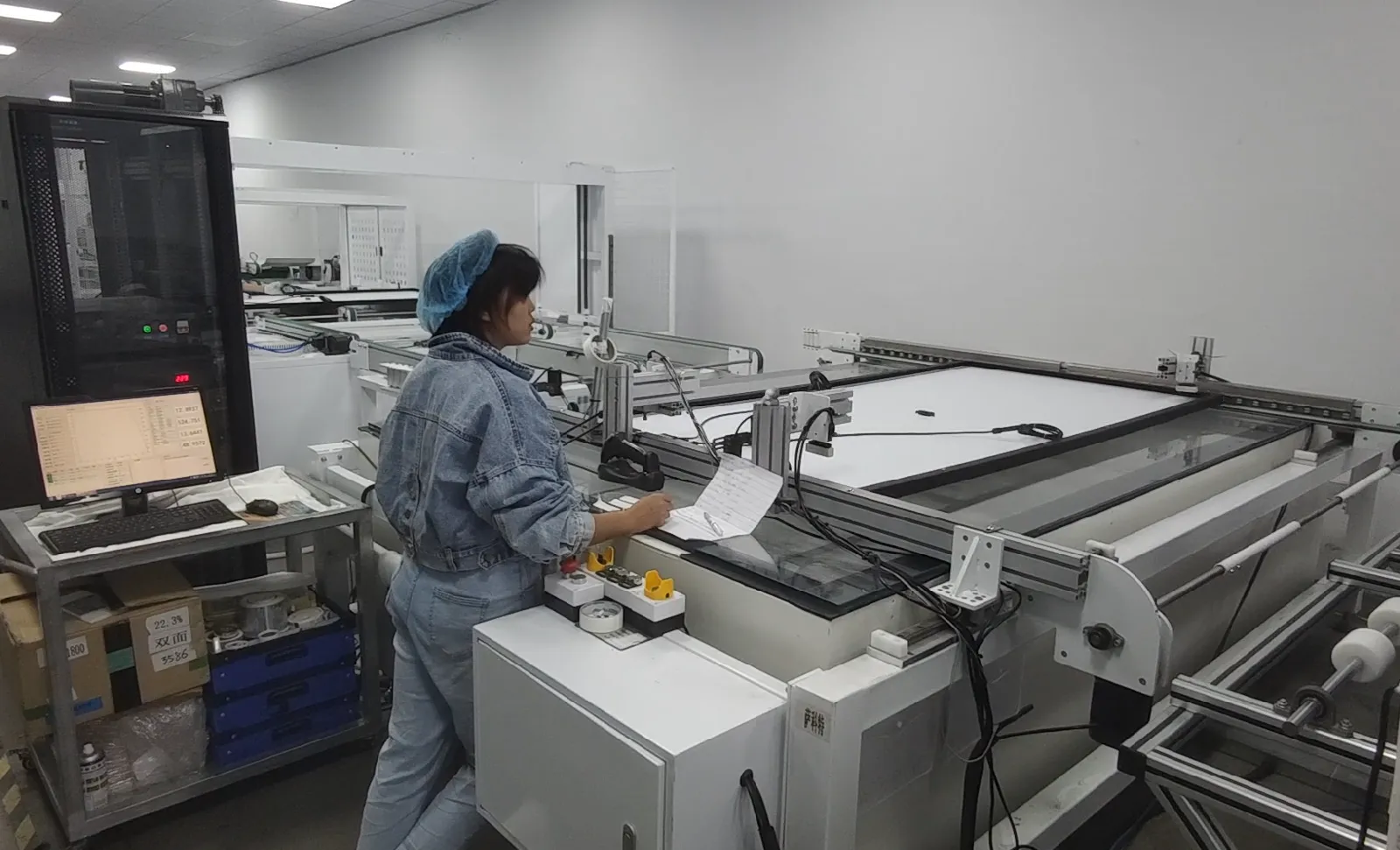
Second: what electrical performance does the module deliver? An IV tester or sun simulator records the current-voltage response under controlled illumination. The result supports power classification and the electrical data associated with the module.
Third: is the product electrically safe? Insulation, hi-pot, and ground-continuity checks address isolation and protective paths according to the construction and applicable quality plan.
Two figures describe how much that release evidence is worth. Inline EL inspection resolves around 0.5 mm per pixel, fine enough to catch microcracks a power measurement alone would pass, and a sun simulator is graded on spectrum match, with the current A+ class window sitting between 0.875 and 1.125. Insulation and hi-pot testing runs from 0.1 kV to 10 kV depending on the module construction and the test plan you are qualifying against.
There is also a fourth question that is easy to overlook: can the factory prove which process history belongs to this physical module?
A barcode or other serial identifier can connect the product to cell or material batches, stringing records, inspection images, lamination recipes, operator or equipment data, IV results, and safety-test outcomes. In an automated factory, this information may be exchanged with a manufacturing execution system. In a smaller factory, the same principle still applies even if data collection is simpler.
Traceability turns test results into a usable production record. It helps investigate recurring defects, isolate affected material, compare recipes, and prevent a rejected unit from being mixed back into accepted stock.
Queues reveal the real factory design
Production output is rarely limited by the machine with the most impressive specification. It is limited by the way cycle times, batches, transfers, inspections, changeovers, maintenance, and quality holds interact over a shift.
Queues are useful evidence because they show where the line is losing coordination.
| What the factory sees | What it may indicate | What to examine |
|---|---|---|
| Finished strings waiting for placement | String production is arriving faster than layup or bussing can absorb it | String discharge pattern, layup cycle, buffer design, defect holds |
| Prepared stacks occupying aisles | Inspection or lamination flow is not clearing incoming work | Material preparation timing, inspection release, batch loading, chamber availability |
| Laminated modules waiting before framing | Cooling, trimming, transfer, or framing is undersized | Conveyor length, cooling time, manual handling, frame preparation |
| Completed modules waiting for test | Test cycle, data transfer, labeling, or sorting cannot match assembly output | Tester configuration, result communication, barcode workflow, reject routing |
| Long stops during product changes | Format flexibility exists on paper but changeover work is poorly defined | Tooling, recipes, material staging, parameter control, operator procedure |
A buffer can protect one process from short disturbances in another, but it is not a cure for permanent mismatch. Too little buffering causes frequent stops. Too much hides problems, increases work in progress, consumes floor space, and allows defects to travel farther before anyone notices a pattern.
The aim is not to eliminate every moment of waiting. It is to know why the waiting exists and whether it protects the process or exposes a design error.
Automate the risk before the spectacle
Automation decisions are often discussed as a choice between a semi-automatic factory and a fully automatic one. A more useful question is where automation removes the greatest operational risk.
Fragile handling is one priority. Repeated lifting and positioning of cells, strings, glass, and large laminates creates opportunities for breakage, scratches, and alignment drift.
Repeatable precision is another. String placement, bussing geometry, adhesive dispensing, framing, and test positioning benefit when the same controlled motion must occur module after module.
Handoffs deserve attention as well. Automatic transfer can reduce queues and manual touches, but only when the connected stations use compatible references, cycle logic, safety controls, and fault recovery.
Finally, automation can improve data capture. Barcode reading, recipe selection, test-result transfer, and reject routing become more reliable when they are built into the process instead of recorded later.
Manual work still has a place. It can provide flexibility during pilot production, product development, lower-volume operation, or steps where judgment is more valuable than speed. The tradeoff is that the process must define training, inspection, ergonomics, and traceability just as carefully as an automatic station defines sensors and interlocks.
The layout begins with inputs, not a floor plan
A supplier cannot design a useful production line from an annual capacity target alone. Annual output is a summary of many operating assumptions. The layout needs the assumptions themselves.
| Project input | Why it changes the line |
|---|---|
| Module drawing and bill of materials | Determines cell preparation, string pattern, stack construction, equipment working range, framing, and junction-box process |
| Required output by shift | Converts the business target into station cycles, batch quantities, parallel equipment, labor, and buffer requirements |
| Product mix and changeover frequency | Affects tooling, recipes, material staging, cleaning, parameter control, and scheduling |
| Quality and certification plan | Defines inspection positions, test equipment, sampling, acceptance logic, rework routes, and record retention |
| Traceability requirement | Determines barcode points, data interfaces, image storage, label printing, and factory-system integration |
| Building and utility information | Sets equipment placement, aisle width, material access, electrical load, compressed air, ventilation, and maintenance space |
| Labor and maintenance model | Changes the boundary between manual work, assisted stations, robotics, spare parts, and technical support |
| Expansion strategy | Determines where space, utilities, conveyors, test capacity, and parallel stations should be reserved |
These inputs also prevent a common layout mistake: drawing a neat line first and then forcing the product and material flow to fit it. The better sequence is product definition, process flow, quality gates, cycle model, equipment configuration, and finally the detailed floor plan.
Sources and related reading
Solar Photovoltaic Manufacturing Basics — U.S. Department of Energy
Ooitech Full Automatic Solar Panel Production Line Equipment
Design backward from the module you need to release
The production line becomes easier to specify when the project defines three outputs: a correct circuit, a durable laminate, and a finished module supported by test and traceability records. Machine selection then follows the process instead of substituting for it.
Ooitech can configure and supply solar panel production systems for customers worldwide, from operator-assisted factories to high-automation lines, with equipment selection, factory layout, installation, commissioning, training, and after-sales support matched to the intended module and production plan.