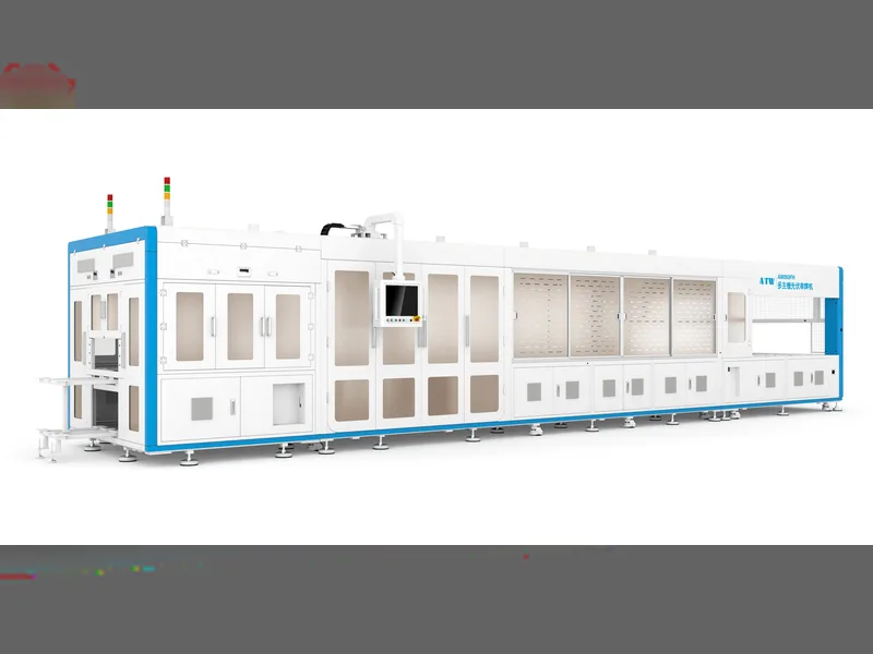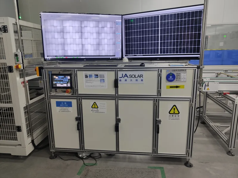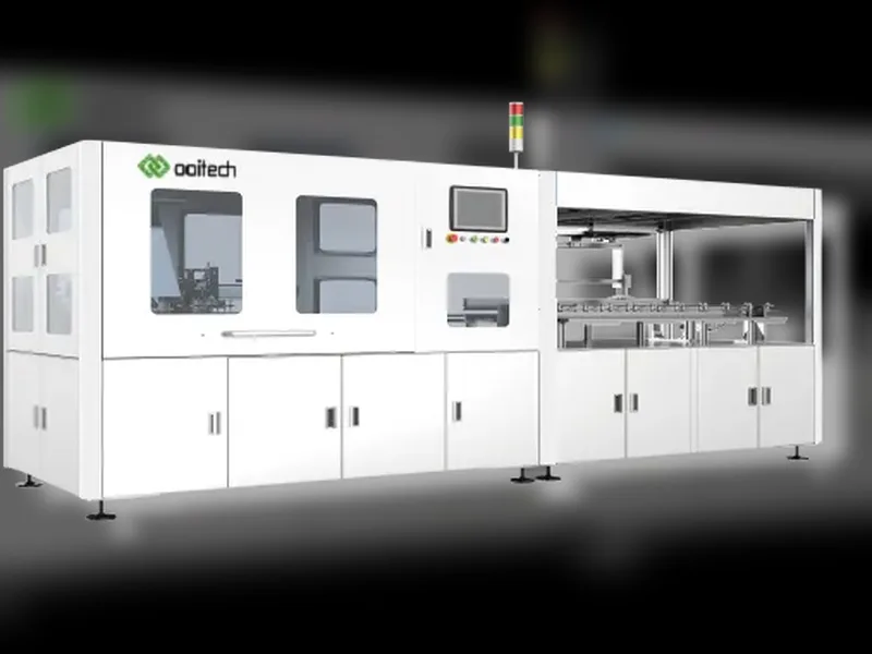
What Machines Are Used to Make Solar Panels, In Order
Table of Contents
Quick answer: Solar panel manufacturing is not one machine. A module factory runs a connected line, and each unit handles one job: cell sorting by current, laser cutting for half or shingled cells, tabbing and stringing to solder cells into strings, layup to arrange strings with encapsulant and glass, lamination to bond the stack, framing to fit the aluminium profile and junction box, then IV testing and sorting of finished modules. Choosing equipment means matching each station's cycle time to the target throughput, because the slowest station sets the line rate. A line is normally described by its annual capacity — 5 MW, 50 MW, 300 MW or 1.2 GW — and the machine count follows from that number. Yield loss compounds across stations, so an extra tenth of a percent of breakage at stringing is much more expensive than it looks.
PV Module Manufacturing · by Jerry, Ooitech
Solar panel manufacturing equipment is not one giant unit. A module factory runs a connected line of machines, and each one handles part of the job: cutting cells, soldering them into strings, arranging the strings, laminating the module, installing the frame and testing the finished panel. Choosing machinery for manufacturing solar panels is therefore a sequencing decision, not a shopping list.
It sounds fairly simple on paper. In actual production, every process affects the next one. A small positioning error during layup may become a bubble or alignment defect after lamination. A poor solder joint may look fine to the human eye but appear as a dark area during EL inspection.
This is why a good solar panel production line must operate as one balanced system, rather than as a random collection of machines.
This guide walks through the solar panel manufacturing equipment on a standard module line, in the order the machines run: cell sorting and laser cutting, stringing, layup, lamination, framing and final testing. Each section explains what the machine does, why it matters, and what to check before you buy it. For budget figures by capacity, see the solar panel production line cost by capacity.
Before looking at the equipment, there is one important distinction.
This article is about a solar module production line—a factory that purchases finished solar cells and assembles them into solar panels. Manufacturing solar cells from silicon wafers is a different process involving wet chemical equipment, diffusion furnaces, PECVD or ALD systems, screen printers, firing furnaces and other specialized machines.
So, what machines are used to make a finished solar panel?
1. Solar Cell Tester and Sorting Machine
A current cell tester is specified against IEC 60904-9:2020: spectral match across 300–1200 nm, irradiance calibrated to 100 mW/cm², light-intensity non-uniformity at or below 2% and short-term instability at or below 1% for an A grade.
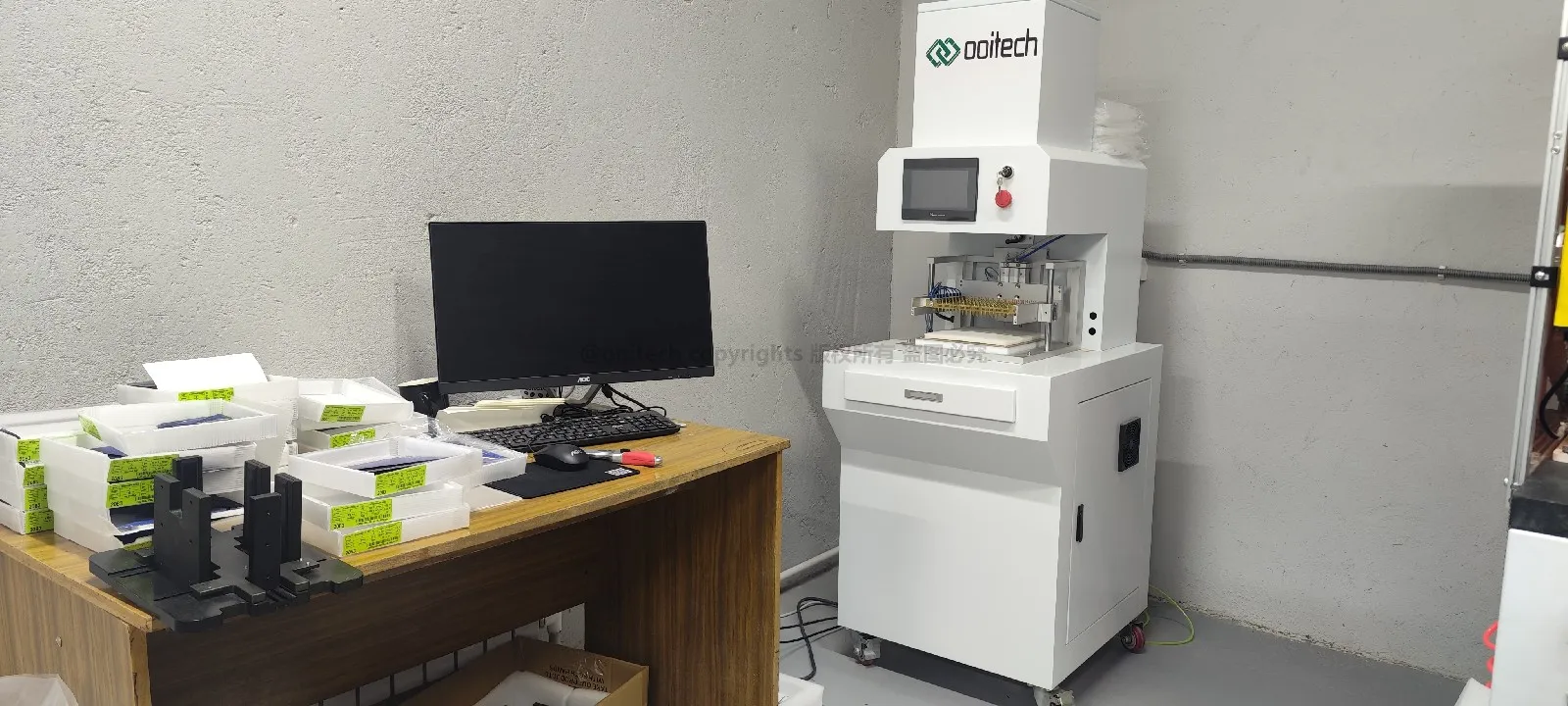
Solar cells from the same production batch are not always electrically identical. Their current, voltage and maximum power may vary slightly. If cells with significantly different electrical characteristics are connected in the same string, the lowest-performing cell can limit the output of the whole string.
A solar cell tester measures parameters such as:
Open-circuit voltage
Short-circuit current
Maximum power
Cell efficiency
I-V curve characteristics
The sorting system then groups cells with similar performance.
Some production lines also use automatic optical inspection or cell-level EL inspection to identify edge chips, hidden cracks, contamination and electrically inactive areas before the cells enter the stringing process.
It may look like a small step, but accurate sorting helps reduce electrical mismatch and improves the consistency of finished modules.
2. Solar Cell Laser Cutting Machine
The figures to hold a supplier to are cutting accuracy at ±0.1 mm or better, and a laser source sized for the job — around 50 W for grooving and up to 300 W where a heating stage runs alongside it.
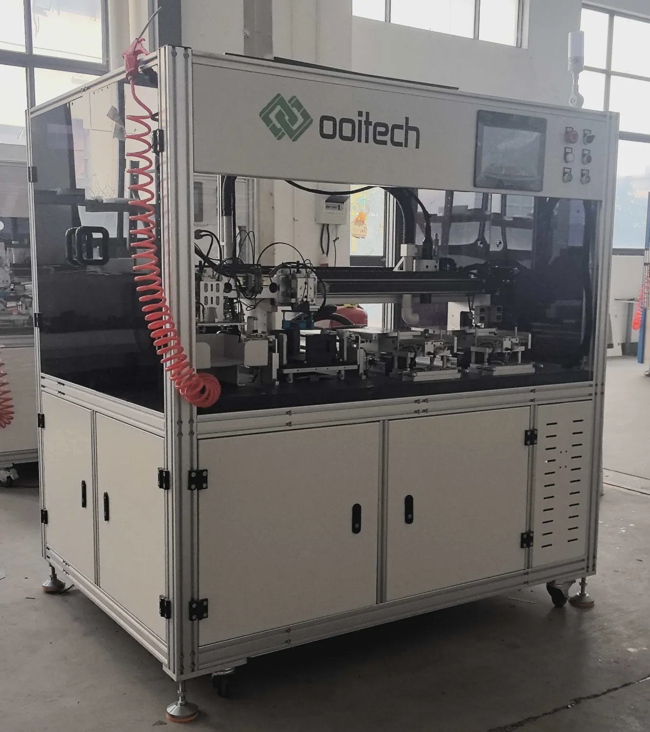
Most modern solar modules use half-cut cells, cut on a solar cell laser cutting machine. Shingled and other special module designs may use even smaller cell sections. In these cases, full-size solar cells must be divided before stringing.
A solar cell laser cutting machine scribes and separates the cells with high precision. Depending on the module design, it may cut cells into halves, thirds or smaller pieces.
Two common cutting methods are used:
Conventional laser scribing followed by mechanical breaking
Non-destructive laser cutting designed to reduce mechanical and thermal stress
Non-destructive cutting is becoming more important as cells become thinner and larger. Microcracks created during cutting may expand during stringing, lamination, transportation or long-term outdoor operation.
If a factory produces only full-cell modules, a laser cutting machine may not be necessary. For half-cell and shingled module production, however, it is a core part of the line.
3. Tabber Stringer Machine
Entry-class stringers run around 1,200 cells per hour and high-speed platforms up to 6,800; positioning accuracy is ±0.15 mm and breakage on Class A cells should be at or below 0.2%. Ribbon width spans 0.35–1.2 mm and cell formats 156–230 mm on machines built today.
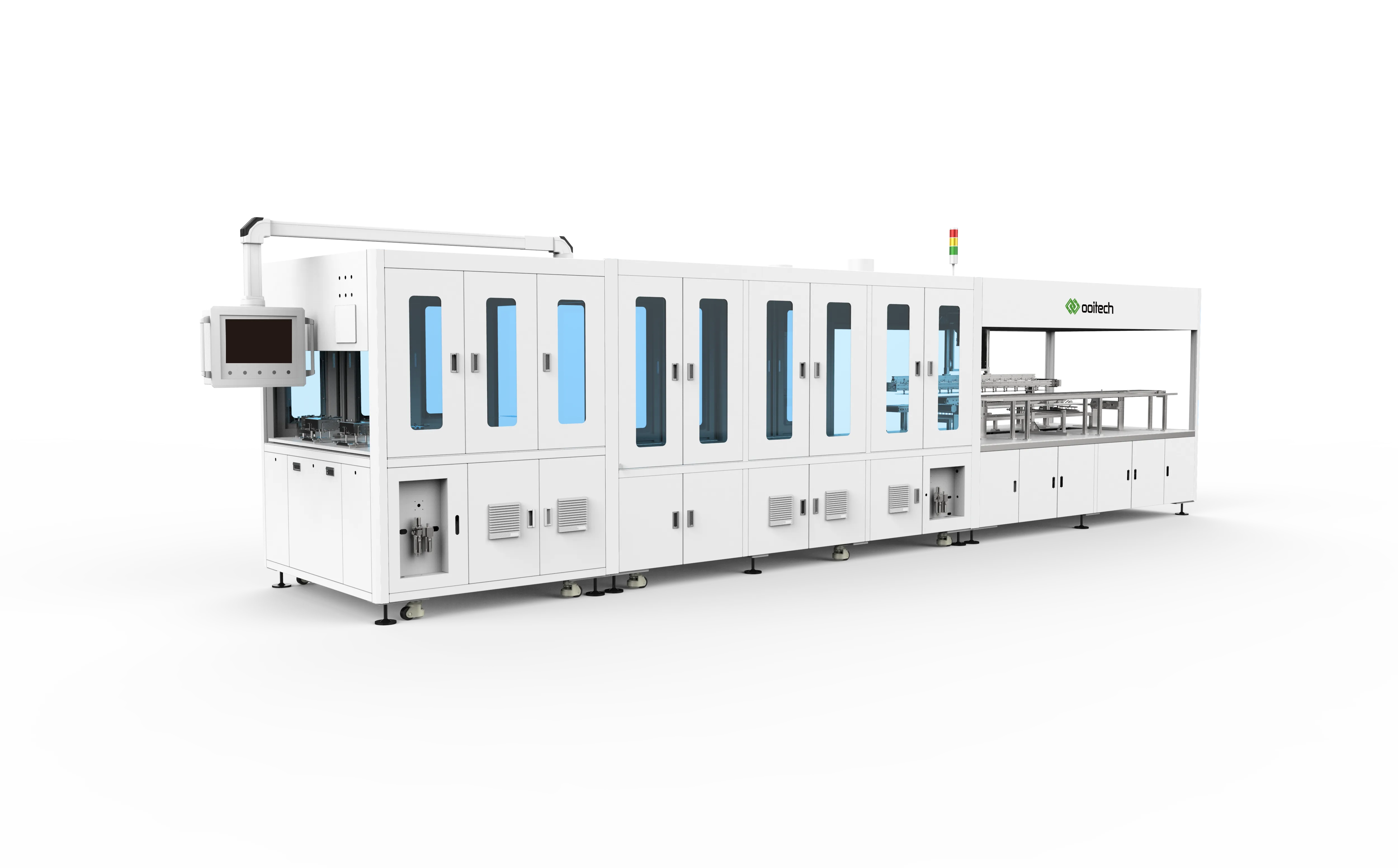
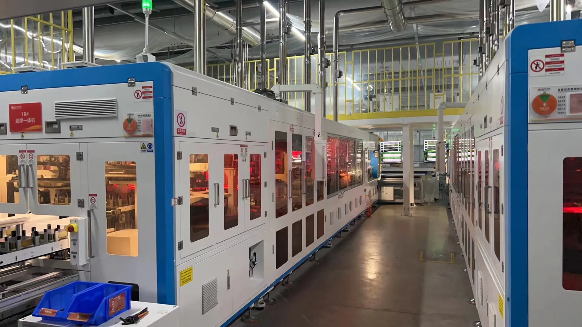
The tabber stringer is often considered the heart of a solar panel production line.
Its main job is to solder photovoltaic ribbon onto individual cells and connect the cells in series to form cell strings. Modern machines usually combine both tabbing and stringing in one automatic process.
A tabber stringer normally handles:
Cell loading and separation
Cell positioning
Ribbon feeding
Flux application
Soldering
String alignment
String cutting and discharge
Vision inspection
The correct stringing method depends on the cell technology.
PERC and TOPCon cells can generally be processed with conventional multi-busbar stringers. HJT cells may require lower-temperature soldering because they are more sensitive to heat. BC, IBC, ABC and HPBC cells need specialized back-contact welding equipment because their positive and negative contacts are both located on the rear side.
Stringer selection should therefore be based on cell size, busbar design, ribbon type, soldering temperature and module structure—not only on the advertised cells-per-hour figure.
4. Inline String EL Inspection
Inline EL on a string is bought on resolution rather than camera count alone: roughly 0.5 mm per pixel is what makes fine microcracks visible, and dual 4.6-megapixel cameras are typical of the current generation.
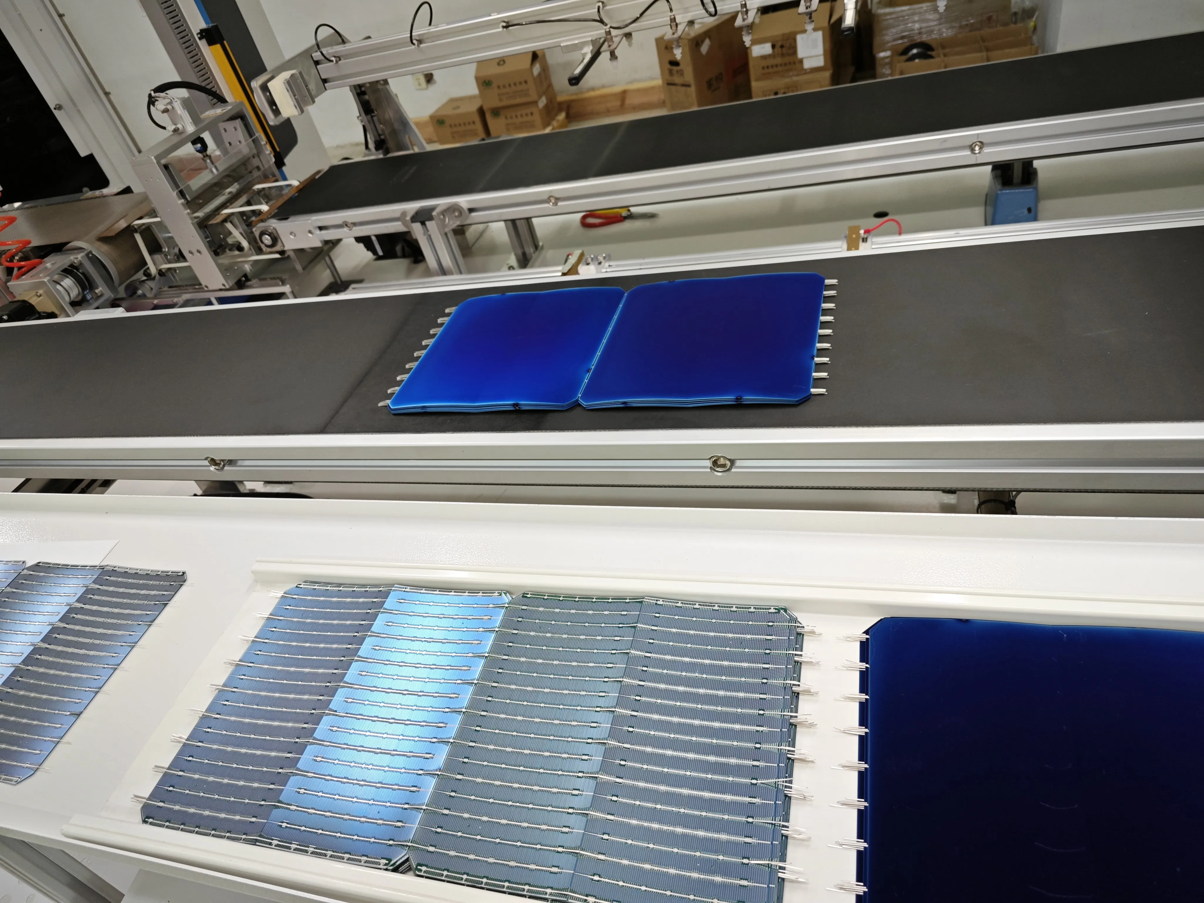
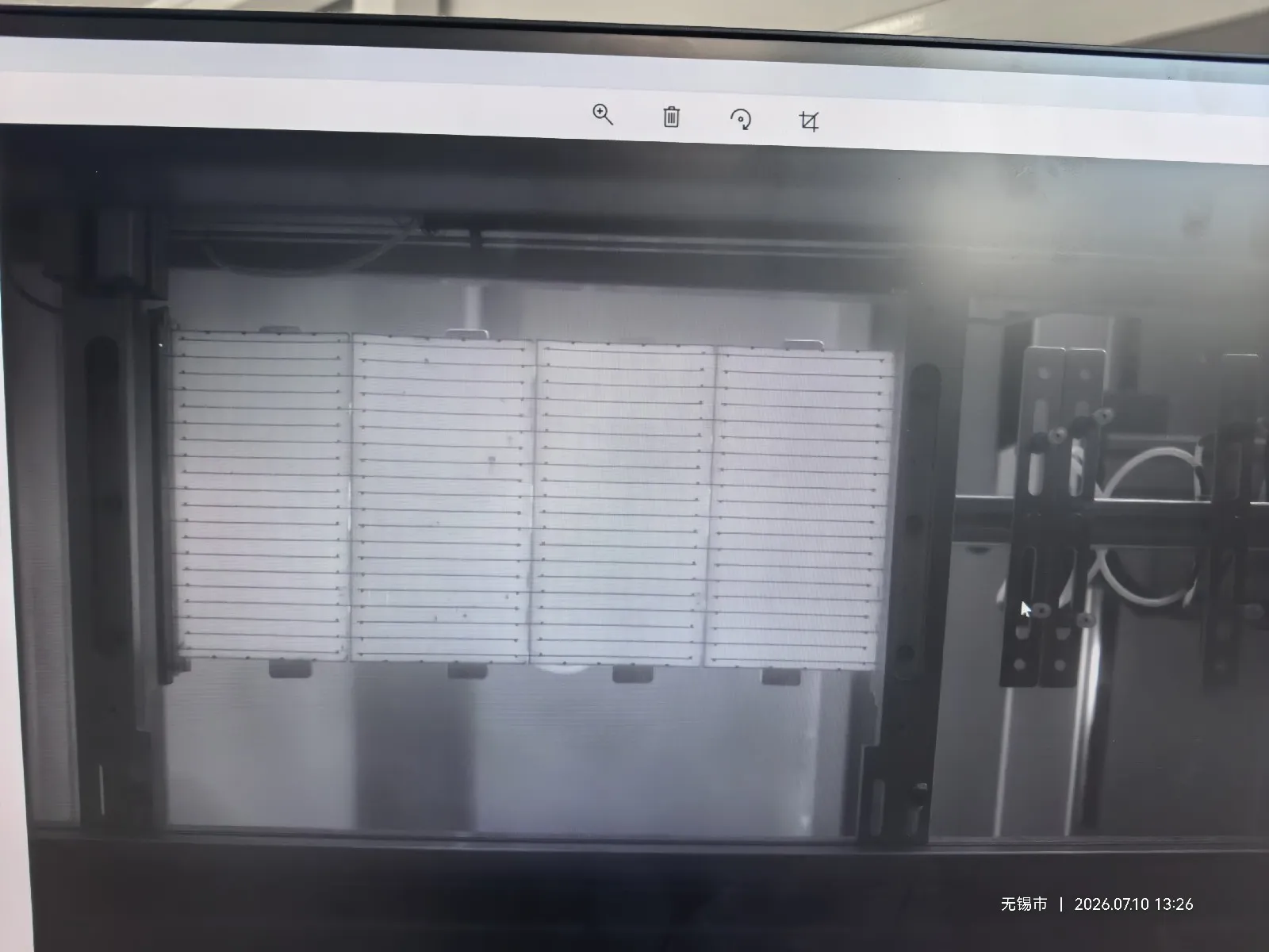
String EL inspection, using a string-level EL tester, is usually an optional function integrated into the tabber stringer rather than a completely separate machine.
In practice, most manufacturers choose this option, especially when producing modules with TOPCon, HJT or BC cells. With these cell technologies, weak solder joints, hidden cracks and electrically inactive areas can be difficult to identify through ordinary visual inspection.
Inline EL inspection checks the string immediately after soldering. A current is applied to the connected cells, and an infrared-sensitive camera captures the electroluminescence image. Cracks, disconnected areas and poor electrical connections appear as abnormal dark regions.
This allows defective strings to be removed before layup and lamination, when repair or replacement is still relatively easy.
An offline string EL tester may still be used for sampling, reinspection or laboratory analysis, but it is not normally required as a separate production station when the stringer already includes inline EL inspection.
5. Solar Glass Loading and Inspection Equipment
The glass it handles is normally 2.0, 2.5 or 3.2 mm thick, with light transmittance above 91.5% and 93.5–94.5% where an anti-reflective coating is applied.
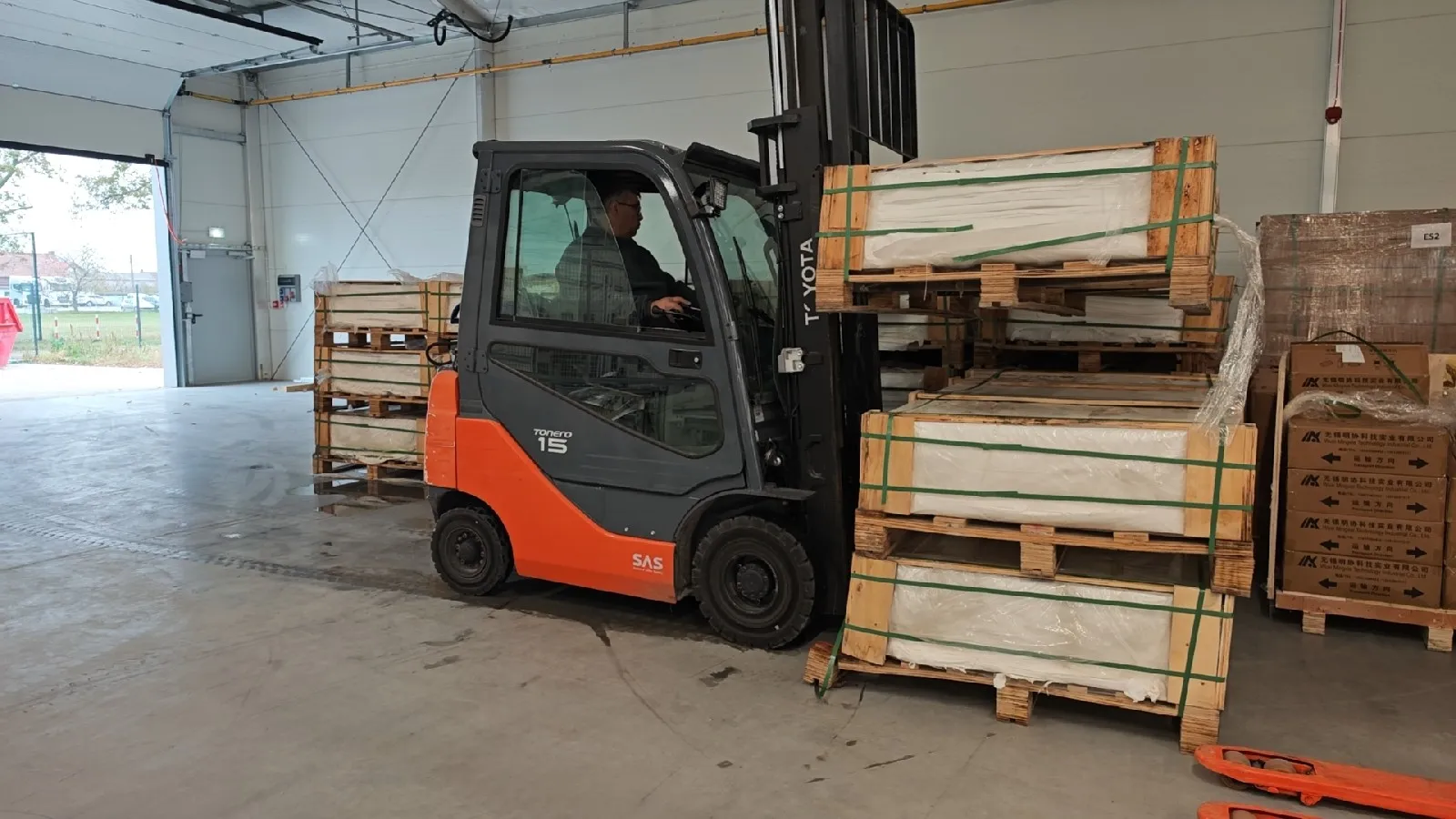
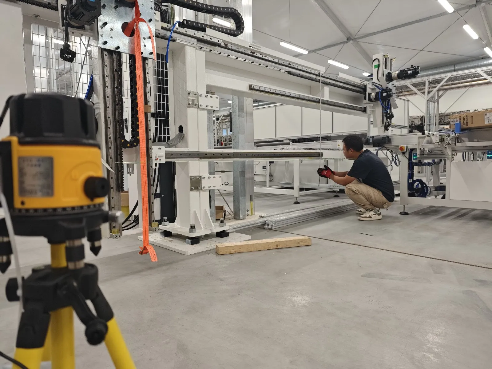
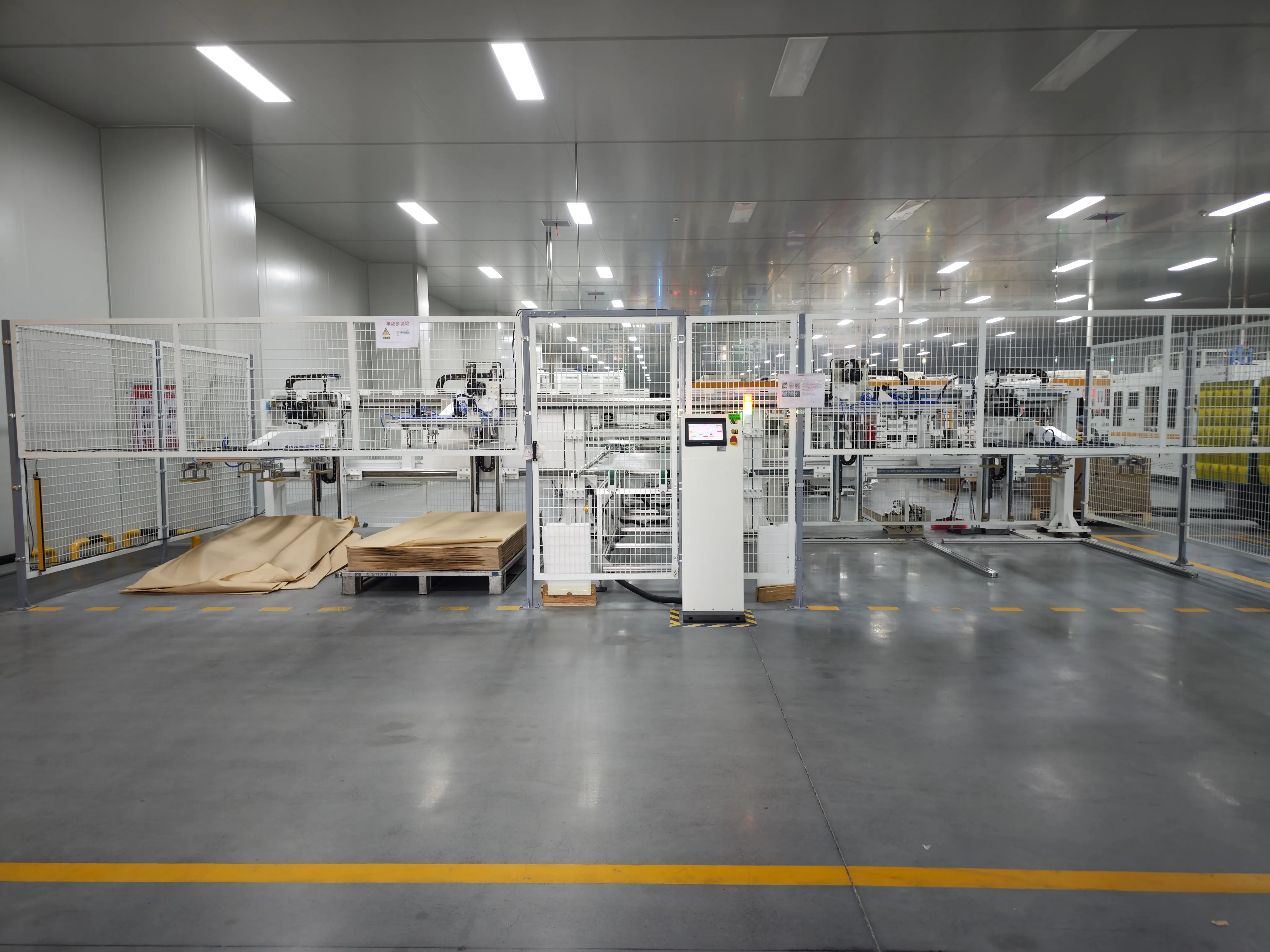
Solar glass supplied to modern module factories is normally washed and prepared by the glass manufacturer. For this reason, a dedicated glass washing machine is generally not required in a standard solar panel production line.
An automatic glass loader places the prepared glass onto the conveyor. Before EVA or POE is laid, the glass is checked for:
Dust and surface contamination
Scratches
Edge damage
Glass chips
Coating defects
Incorrect dimensions
The front glass forms the base of the module stack, so its position must remain stable during the following material-laying and cell-layup processes.
6. EVA, POE and Backsheet Cutting and Laying Machines
The materials carry their own numbers before the machine does: EVA encapsulant with 75–85% gel content after curing and peel strength above 80 N/cm to glass, cut and laid to the module drawing.
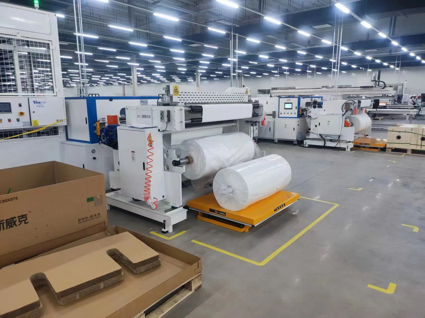
Before layup, the encapsulant and rear-layer materials must be cut to the correct module dimensions on an EVA and backsheet cutting machine.
An automatic cutting and laying machine can prepare materials such as:
EVA film
POE film
TPT or other backsheets
Insulation strips
Busbar isolation materials
After cutting, the machine lays the encapsulant onto the glass automatically.
For glass-glass modules, the polymer backsheet is replaced by a second piece of glass. The line layout, laminator and handling equipment must therefore be designed for the additional weight and the different module structure.
Small factories may cut EVA and backsheet materials manually. Automatic cutting and laying becomes more valuable as production capacity increases because it improves dimensional consistency and reduces material waste.
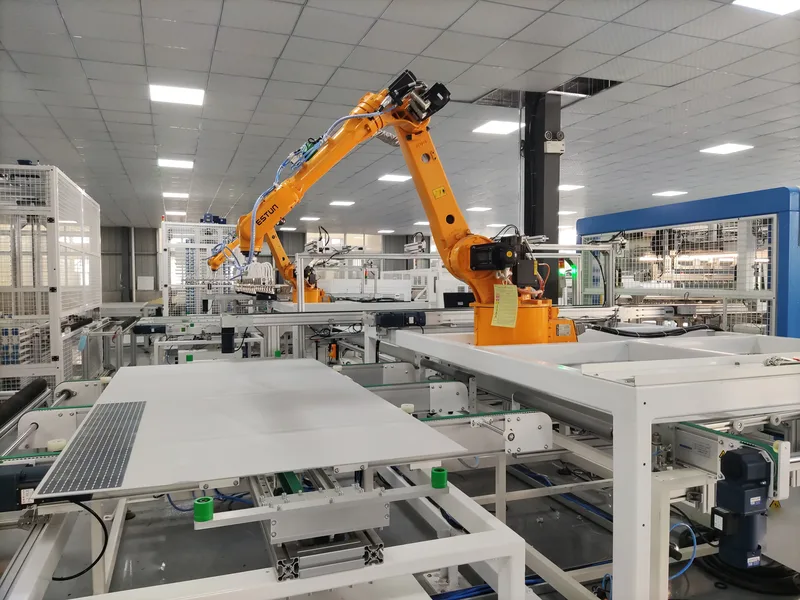
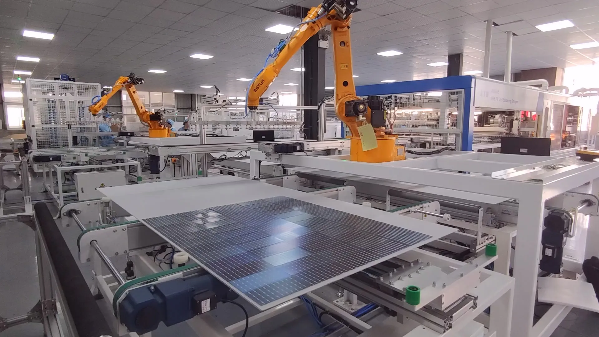
7. Automatic Layup Machine
Layup is specified as a cycle time of 48 seconds or less per module, glass alignment accuracy of ±0.1 mm, and a working range covering glass with a long side from 1,600 to 2,600 mm.
The automatic layup machine takes completed cell strings and positions them on the glass and encapsulant.
This is a precision process. String spacing, cell alignment and the distance between the cells and glass edges must stay within the specified tolerances.
Poor alignment is easy to notice on a finished panel, but appearance is not the only concern. Incorrect string positions may also affect encapsulation, edge sealing and long-term module reliability.
An automatic layup machine normally uses:
Industrial robots or gantry systems
Vacuum grippers
Vision cameras
Automatic position correction
String spacing controls
Glass-position detection
Some production lines use a separate layup machine. Others combine string positioning, layup and bussing in one integrated unit.
8. Bussing Machine
An automatic bussing machine runs a 17–18 second cycle and holds utilisation above 99%, and it has to cover 5 to 30 busbars as multi-busbar layouts multiply.
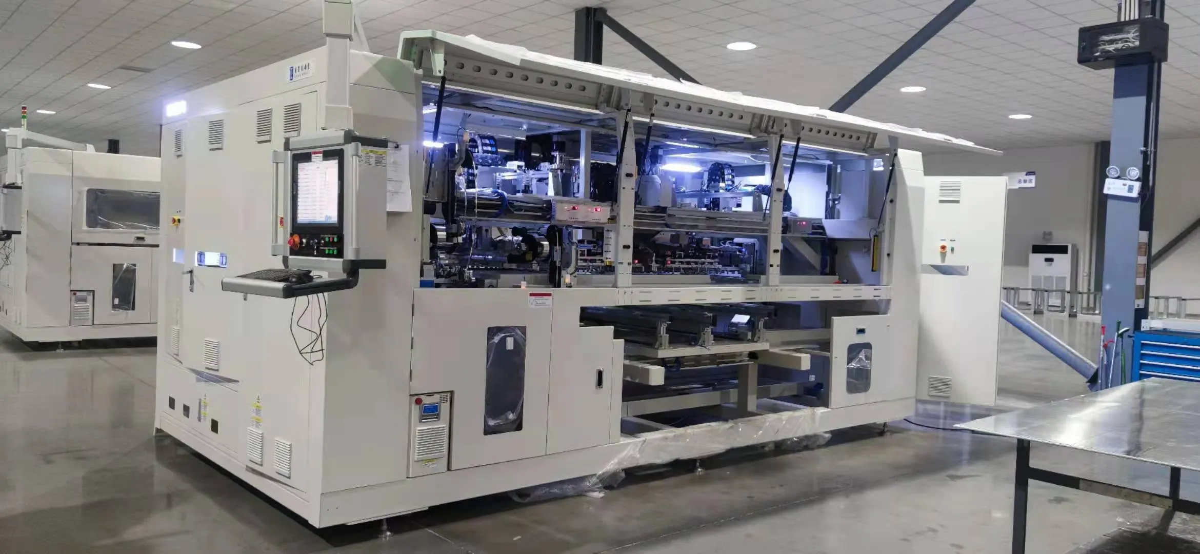
After the strings are positioned, they must be electrically connected with busbar ribbon, usually on an automatic bussing machine.
An automatic bussing machine welds or solders the string terminals together according to the electrical design of the module. It may also bend, cut and position the busbar ribbons automatically.
Half-cell modules require particular attention because their upper and lower cell sections are generally connected in parallel. The lead-out point is normally located near the middle of the panel instead of at the top.
The bussing process must control:
Busbar position
Welding or soldering temperature
Joint strength
Ribbon shape
String spacing
Lead-out ribbon position
A weak bussing connection may cause power loss, excessive local heating or complete circuit failure.
On a small semi-automatic line, bussing can be completed manually with soldering tools and positioning templates. Higher-capacity factories normally use automatic bussing machines for better consistency and throughput.
9. Pre-Lamination EL Tester and Visual Inspection
Pre-lamination EL is bought on image resolution — 4,928 × 3,264 pixels on a current tester — and on a working area large enough for the largest module the line intends to build.
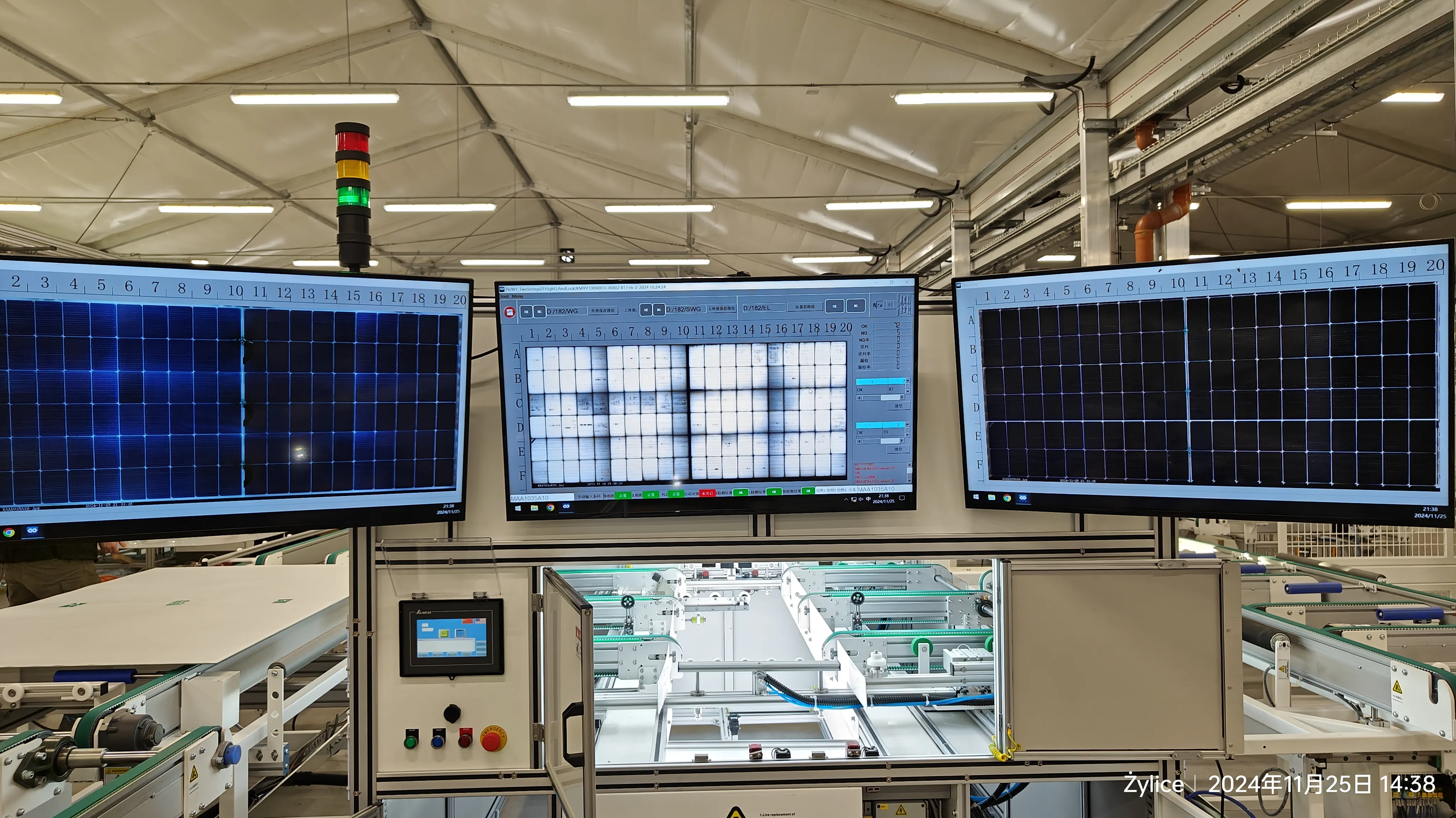
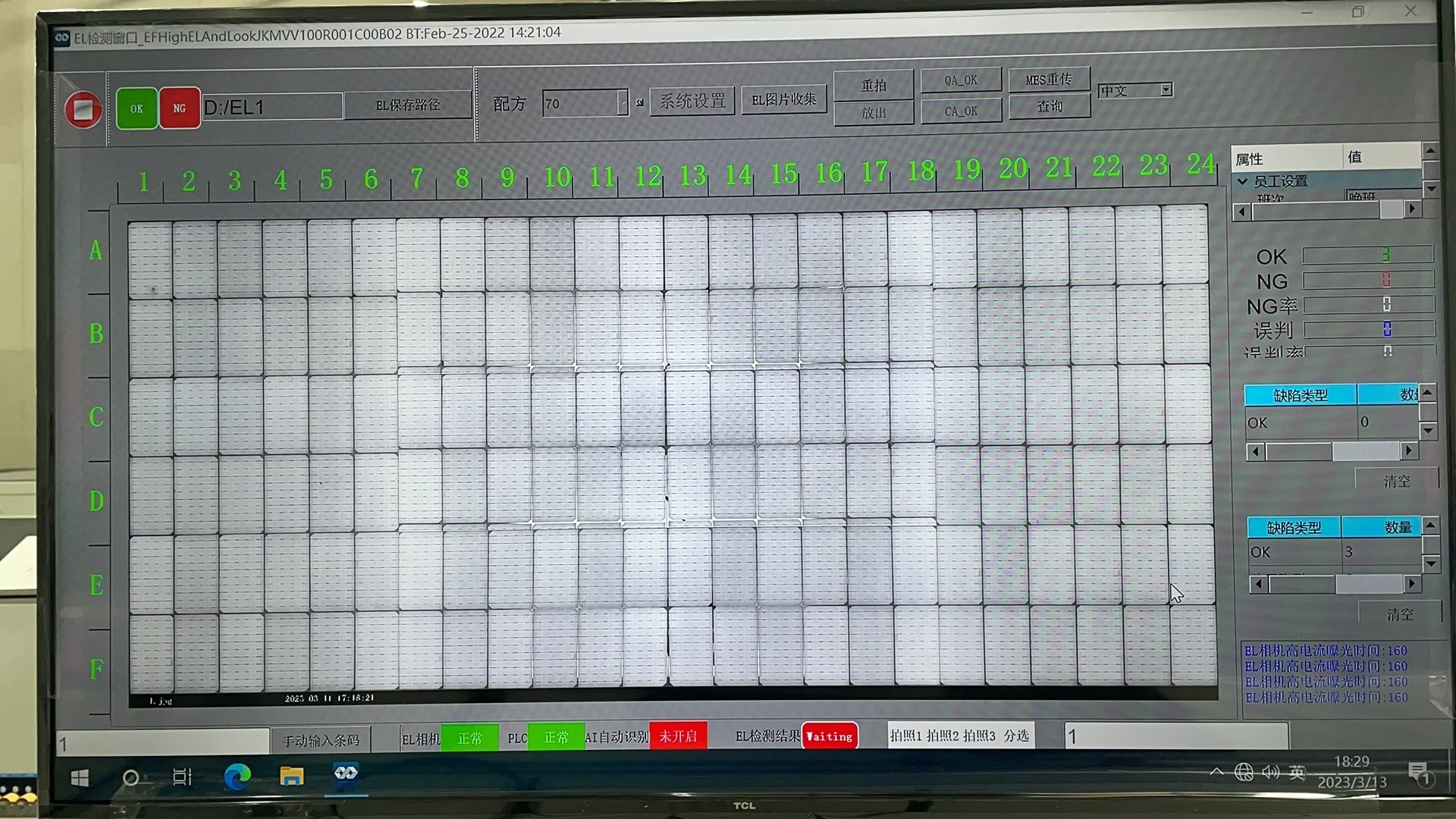
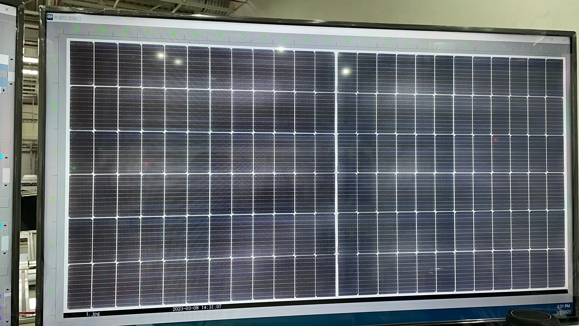
Before lamination, the assembled module should pass visual inspection and EL testing.
This is the last practical opportunity to repair many production defects. Operators or automatic inspection systems check for problems such as:
Cracked cells
Misaligned strings
Missing ribbons
Poor bussing connections
Incorrect lead-out positions
Contamination inside the module
Wrinkled or displaced encapsulant
Incorrect backsheet placement
The pre-lamination EL tester checks the electrical condition of the complete cell circuit before it is permanently sealed.
Lamination is effectively irreversible. If a defect is found after lamination, the repair cost is much higher, and in many cases the entire module must be scrapped.
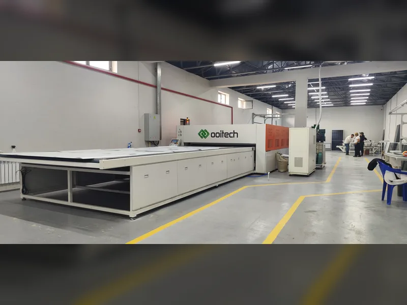
10. Solar Panel Laminator
The process window is 140–150°C while the encapsulant crosslinks, and the recipe is a sequence of vacuum stages, heating ramp, pressure and dwell rather than a single temperature setting.
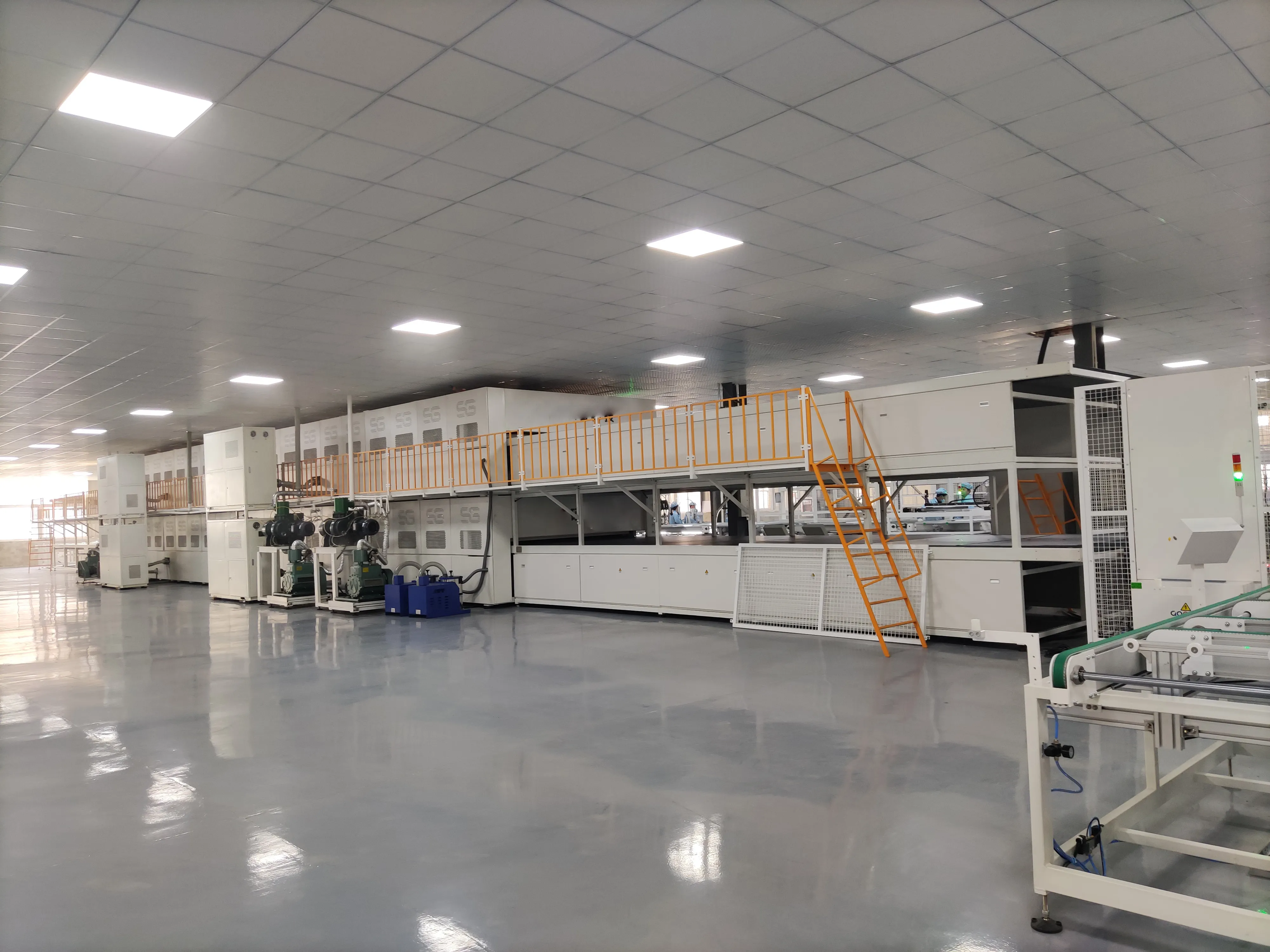
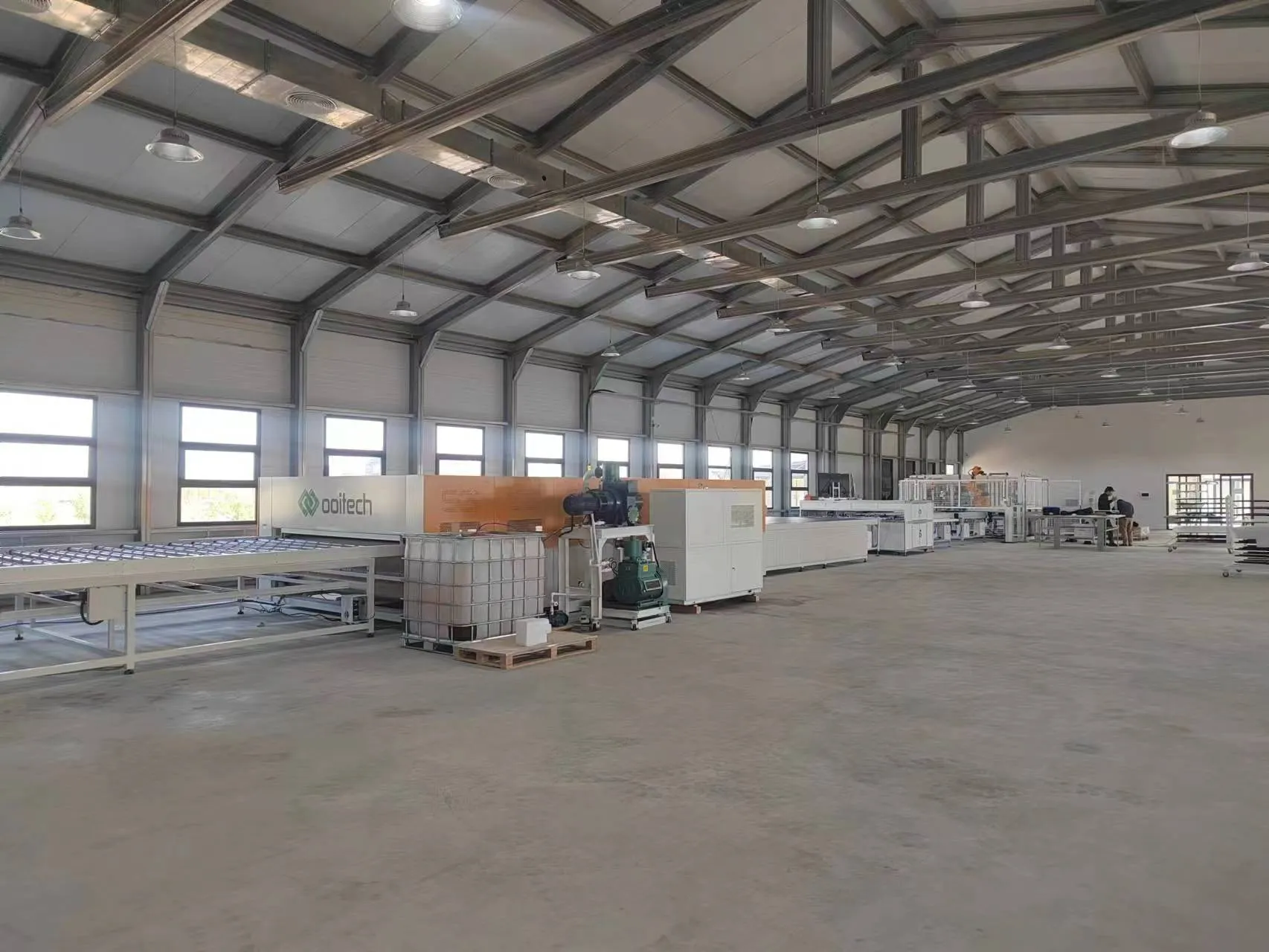
The laminator seals the glass, encapsulant, solar cells and backsheet—or rear glass—into one durable structure.
Inside the laminator, vacuum removes trapped air from the module stack. Heat and pressure then cure the EVA or POE, bonding all layers together.
The lamination recipe depends on:
Encapsulant type
Module size
Glass thickness
Glass-backsheet or glass-glass structure
Cell technology
Material supplier requirements
A typical lamination cycle may take around 10 to 20 minutes, although the actual time varies with the materials and equipment.
The laminator is often the slowest major process in the production line. A factory may therefore need several laminators operating in parallel.
This is an important point when calculating production capacity. Installing faster stringers will not increase the final module output if the lamination section cannot process panels at the same rate.
Lamination quality directly affects adhesion, electrical insulation, moisture resistance and the expected service life of the module.
11. Trimming and Post-Lamination Inspection Equipment
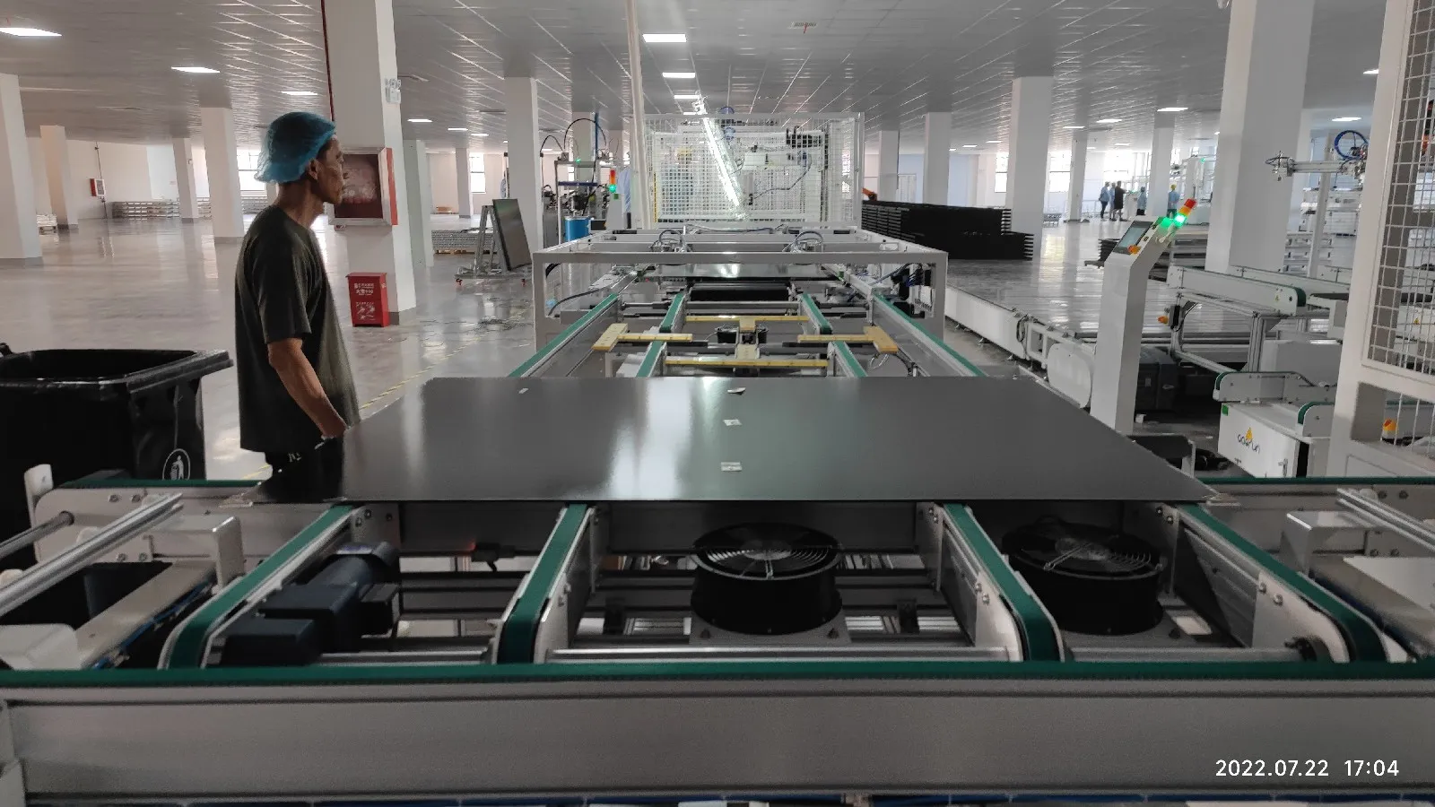
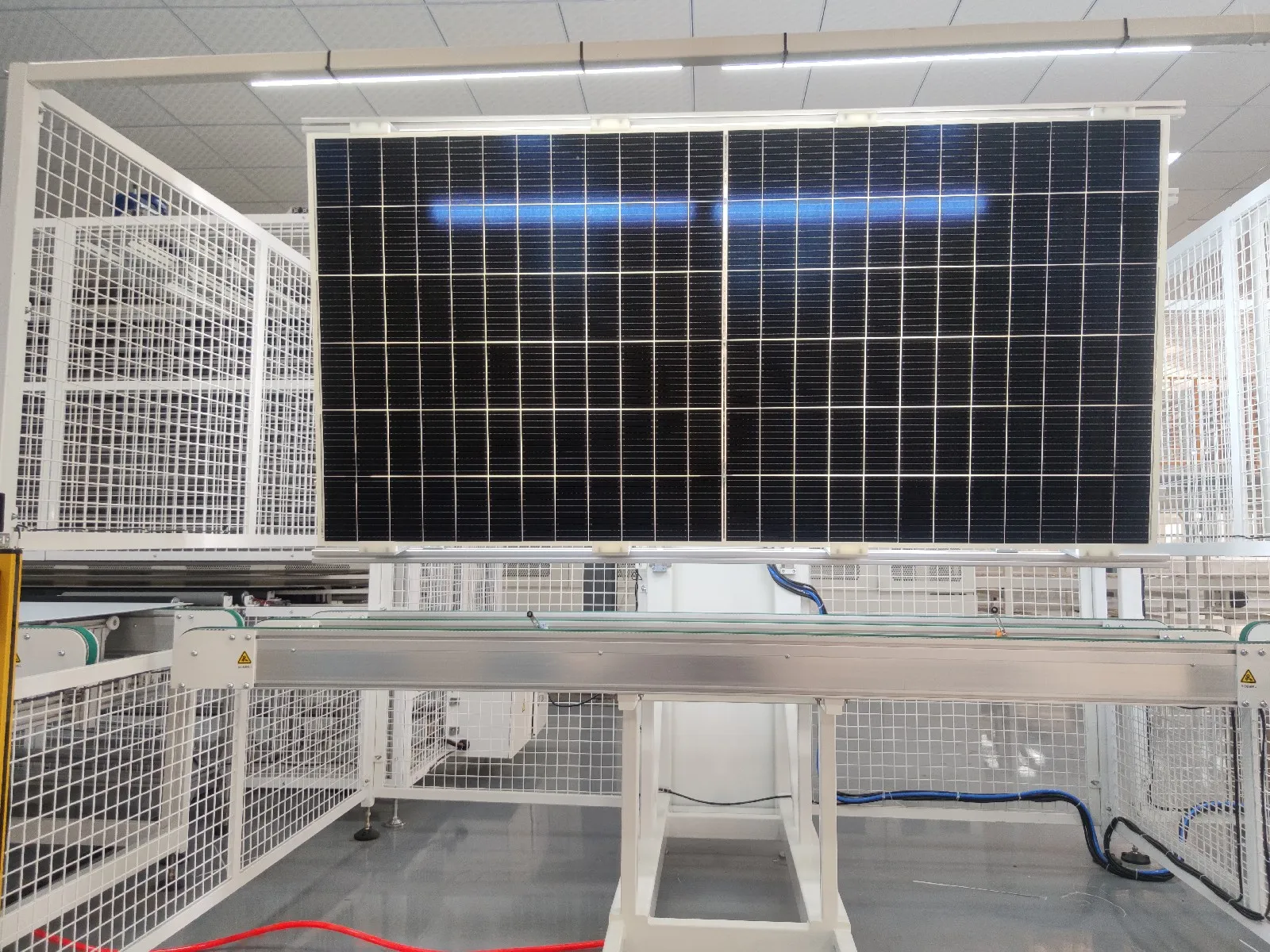
After lamination, excess EVA, POE or backsheet remains around the module edges. This material must be removed before framing.
On a small line, operators may trim the edges manually. A high-capacity automatic line normally uses an edge-trimming machine.
The laminated module is also inspected for:
Air bubbles
Delamination
Encapsulant overflow
Scratches
Glass damage
Cell movement
String displacement
Contamination inside the laminate
Automatic turnover units make it easier to inspect both sides of the module without relying on manual lifting.
12. Frame Gluing and Framing Machine
Framing accuracy is held to ±1 mm with the diagonal difference inside ±1.5 mm, on a working range up to 2,000 × 1,100 × 50 mm; frame gluing runs a stroke of up to 2,500 mm.
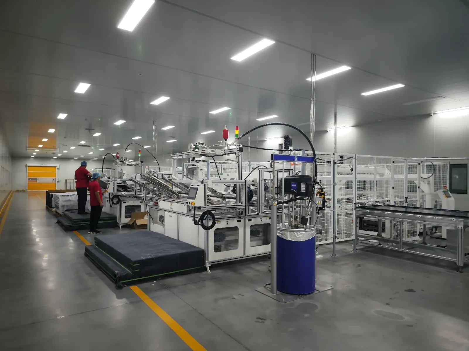
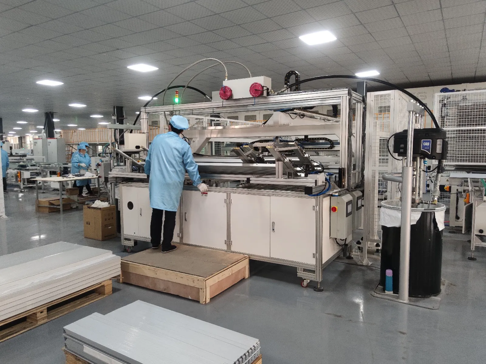
Most conventional solar panels use an aluminum frame, applied by a framing machine, to protect the glass edges and provide mechanical support during transportation and installation.
The framing section may include:
Automatic frame gluing machine
Aluminum frame loading system
Corner-key insertion equipment
Frame assembly machine
Pneumatic or hydraulic framing machine
Frame punching equipment
Sealant is applied inside the aluminum profiles before the four frame sections are pressed around the laminated module.
The finished frame must be square, secure and properly sealed. Common framing defects include loose corners, insufficient sealant, excessive sealant, scratches and incorrect frame dimensions.
Frameless glass-glass modules may not require this process, depending on the product design.
13. Junction Box Installation Machines
Junction-box welding runs a cycle of 16 seconds or less at ±0.1 mm CCD positioning, with the qualified rate for welding tension expected at or near 100%.
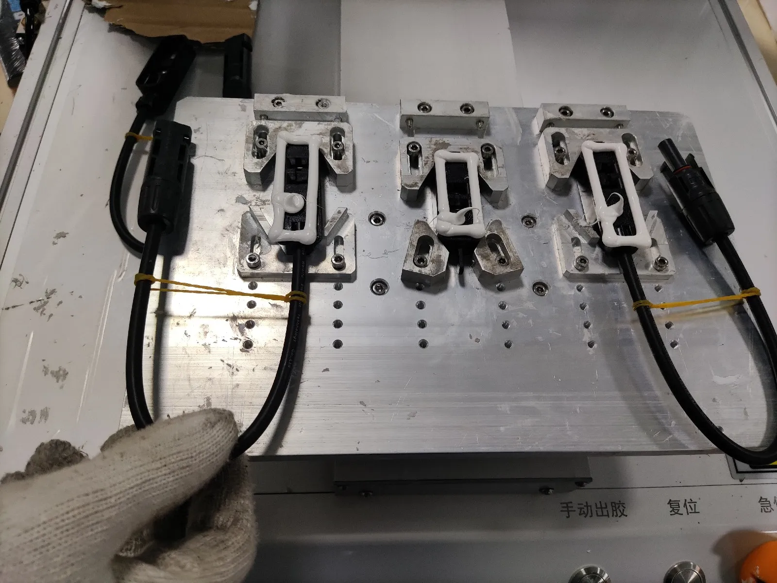
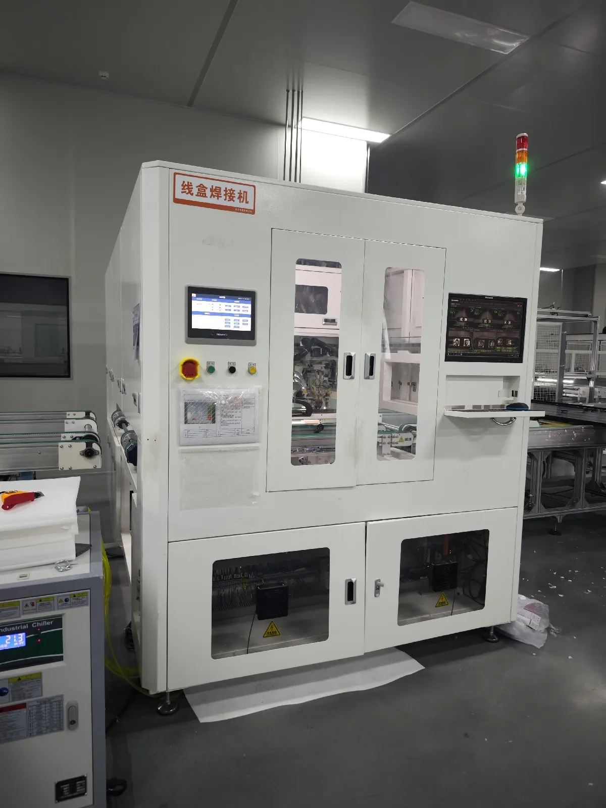
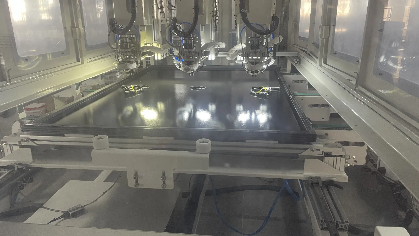
The junction box collects the electrical output from the cell circuit and provides the connection between the module and the external PV system. It is attached on a junction box welding machine.
The junction box process may include:
Junction box positioning
Silicone or adhesive dispensing
Lead-out ribbon soldering
Automatic terminal welding
AB glue filling
Potting
Cable and connector inspection
A junction box soldering machine connects the module’s lead-out ribbons to the junction box terminals. A dispensing or potting machine then applies sealant or filling material to protect the electrical connections against moisture, movement and corrosion.
The adhesive and potting material must receive sufficient curing time before final testing and packaging.
14. Final EL Tester
Final EL is normally the higher-resolution of the two checks, with four cameras at 5,440 × 3,648 pixels and imaging precision around 0.5 mm per pixel on a current machine.
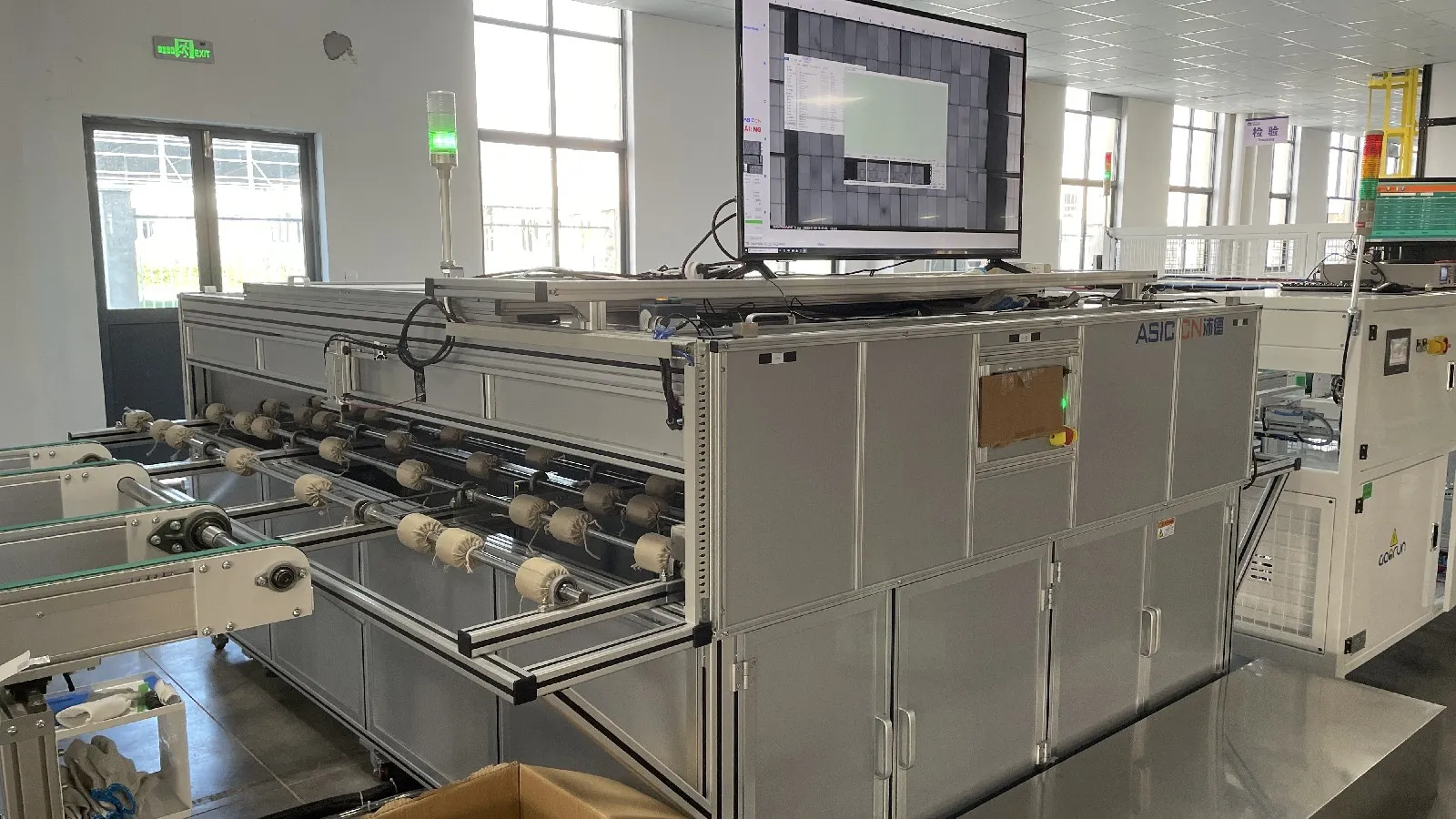
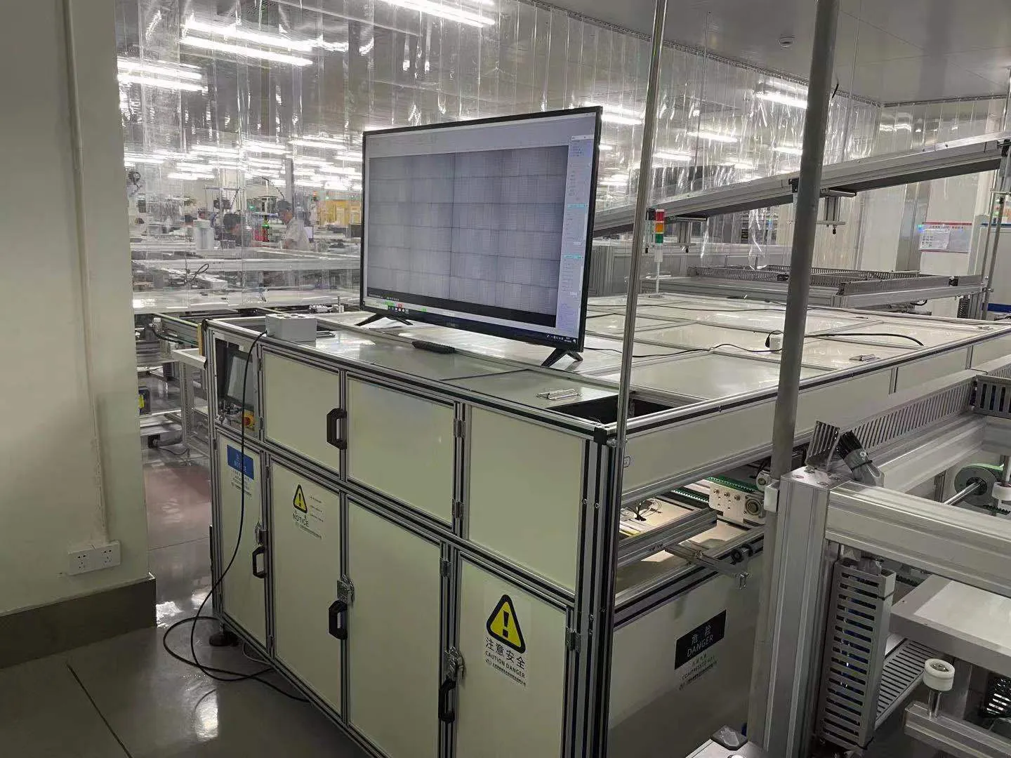
A second EL test is normally performed after lamination or final module assembly.
This test is necessary because new microcracks may be introduced during lamination, trimming, framing or material handling.
The final EL image can reveal:
Cell microcracks
Broken cells
Disconnected fingers
Poor solder joints
Broken busbars
Electrically inactive areas
String interruptions
Automatic image-analysis software can help classify defects, but the manufacturer still needs clear acceptance standards. The system must define which defects are acceptable, which require rework and which result in rejection.
15. Solar Simulator and I-V Tester
A sun simulator is graded on spectrum match, where the A+ class window sits between 0.875 and 1.125, on irradiance from 200 to 1,200 W/m² and a cycle time around 25 seconds.
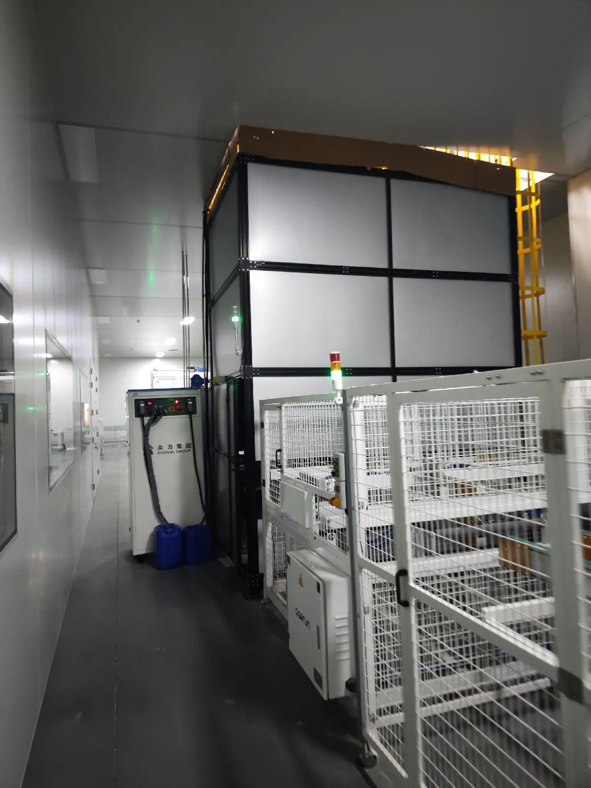
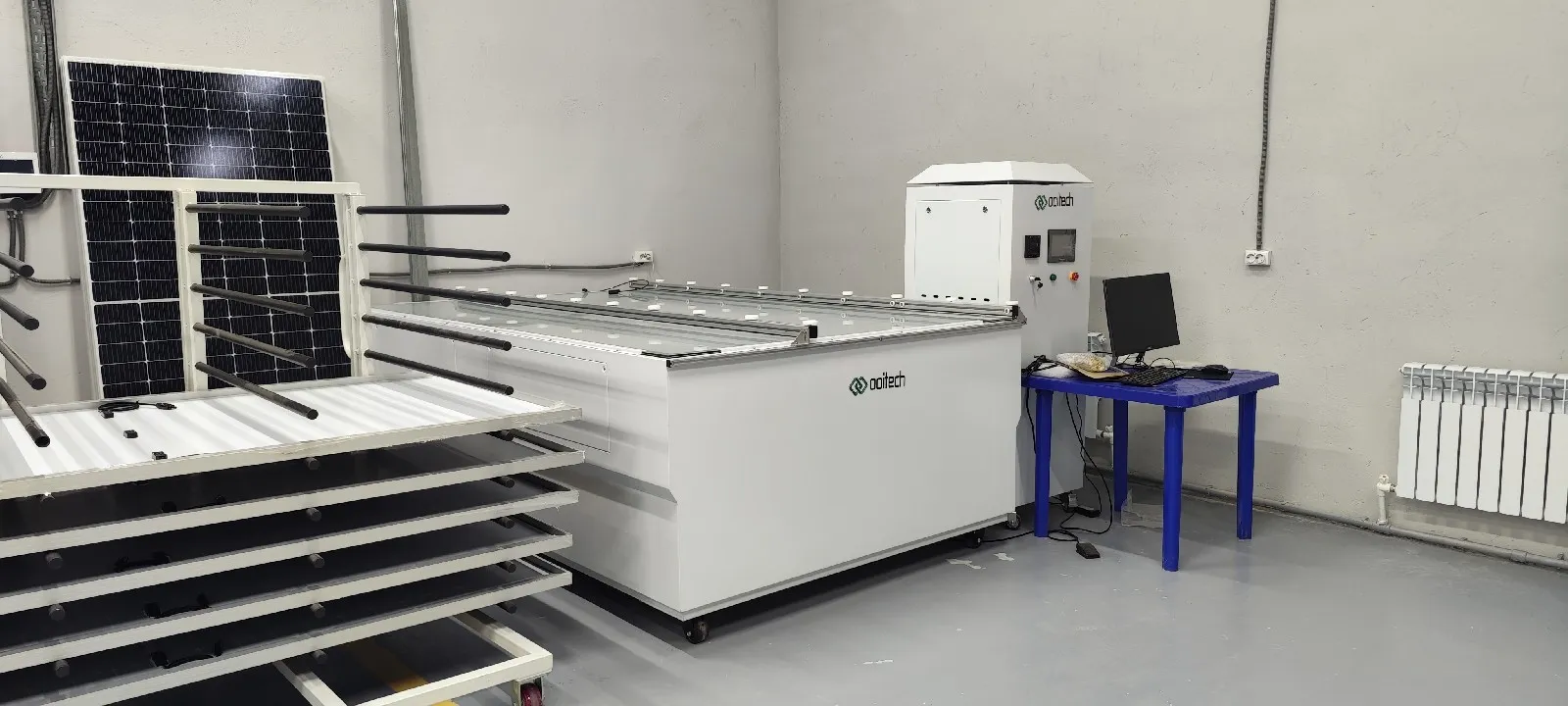
The solar simulator, also known as a flash tester or I-V tester, measures the electrical performance of the finished solar panel under controlled illumination.
The tester records parameters including:
Maximum power
Open-circuit voltage
Short-circuit current
Operating voltage
Operating current
Fill factor
Module efficiency
Complete I-V curve
The measured power is used to grade the panel and generate its nameplate or production label.
The solar simulator should have suitable spectral match, light uniformity and stability. Its testing speed must also match the production capacity of the rest of the line. Otherwise, finished panels will begin accumulating in front of the testing station.
16. Safety Testing Equipment
Hi-pot and insulation testers run from 0.1 kV to 10 kV with leakage current measured in milliamps, and ground-continuity testing applies a programmable 5–60 A across a range reaching down to milliohms.
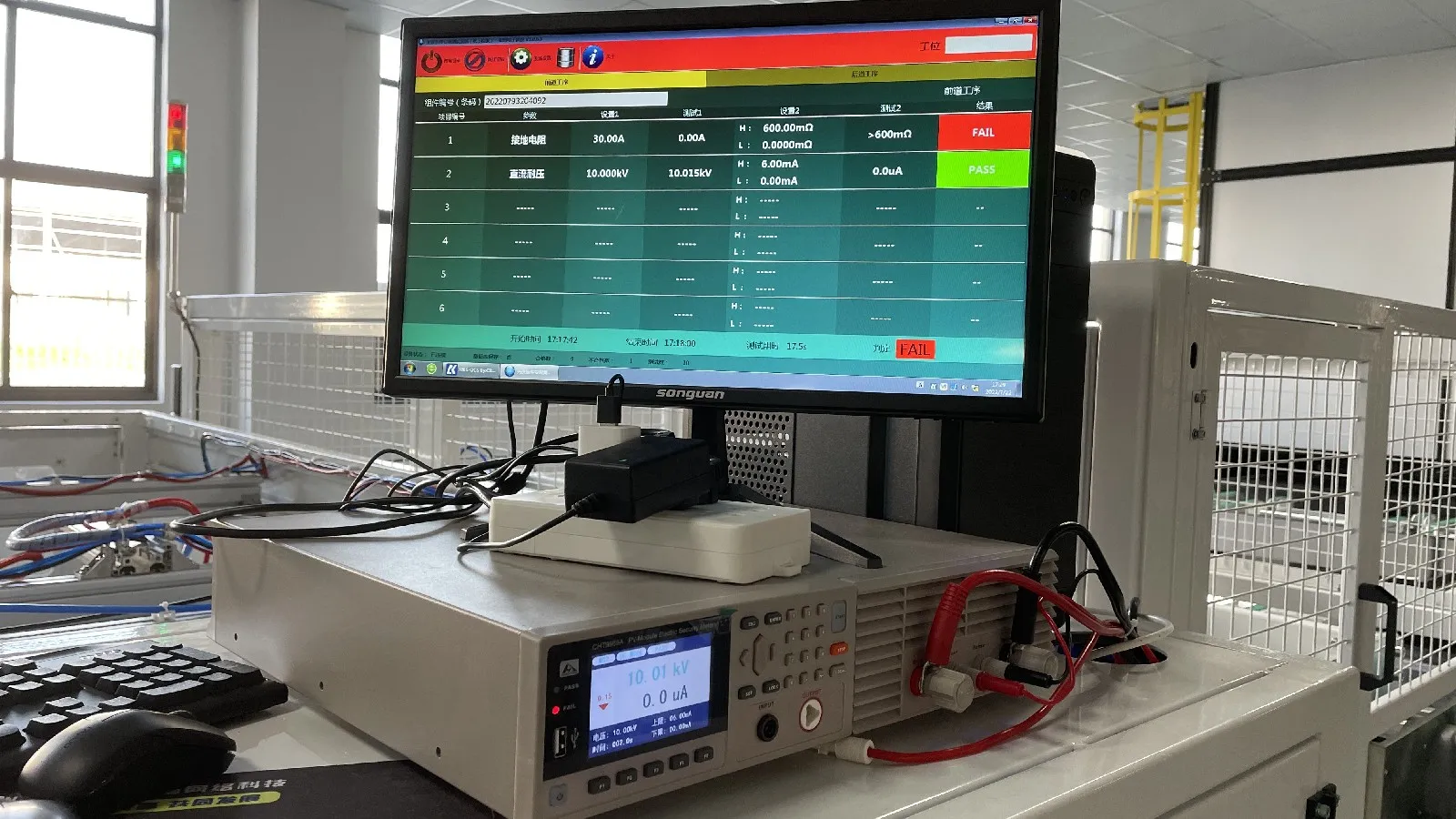
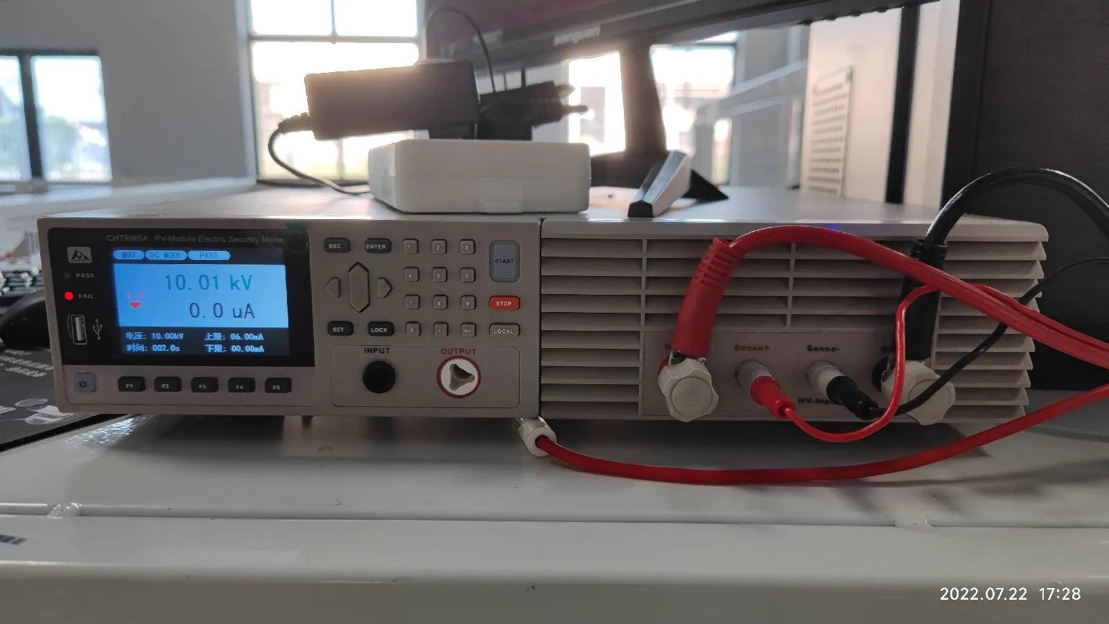
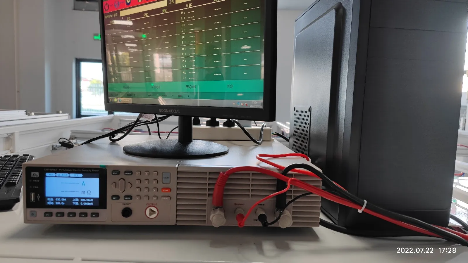
Electrical output is only one part of final quality control. The panel must also be electrically safe.
Common safety-testing equipment includes:
Hi-pot tester
Insulation resistance tester
Ground continuity tester
Leakage current tester
The hi-pot test applies high voltage between the internal electrical circuit and the module frame to verify insulation integrity.
The ground continuity test measures the electrical connection between the aluminum frame and its grounding points. Insulation testing checks whether the module can operate safely without dangerous leakage paths.
These are essential production tests, not optional quality checks.
17. Labeling, Sorting and Packaging Line
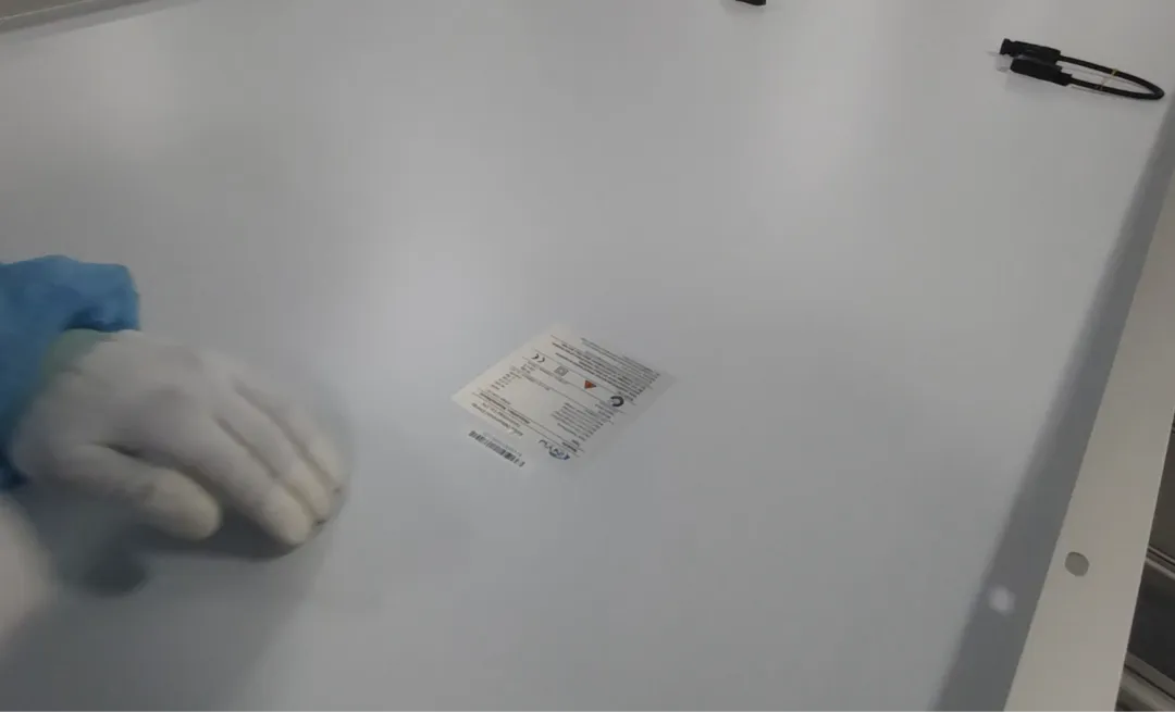
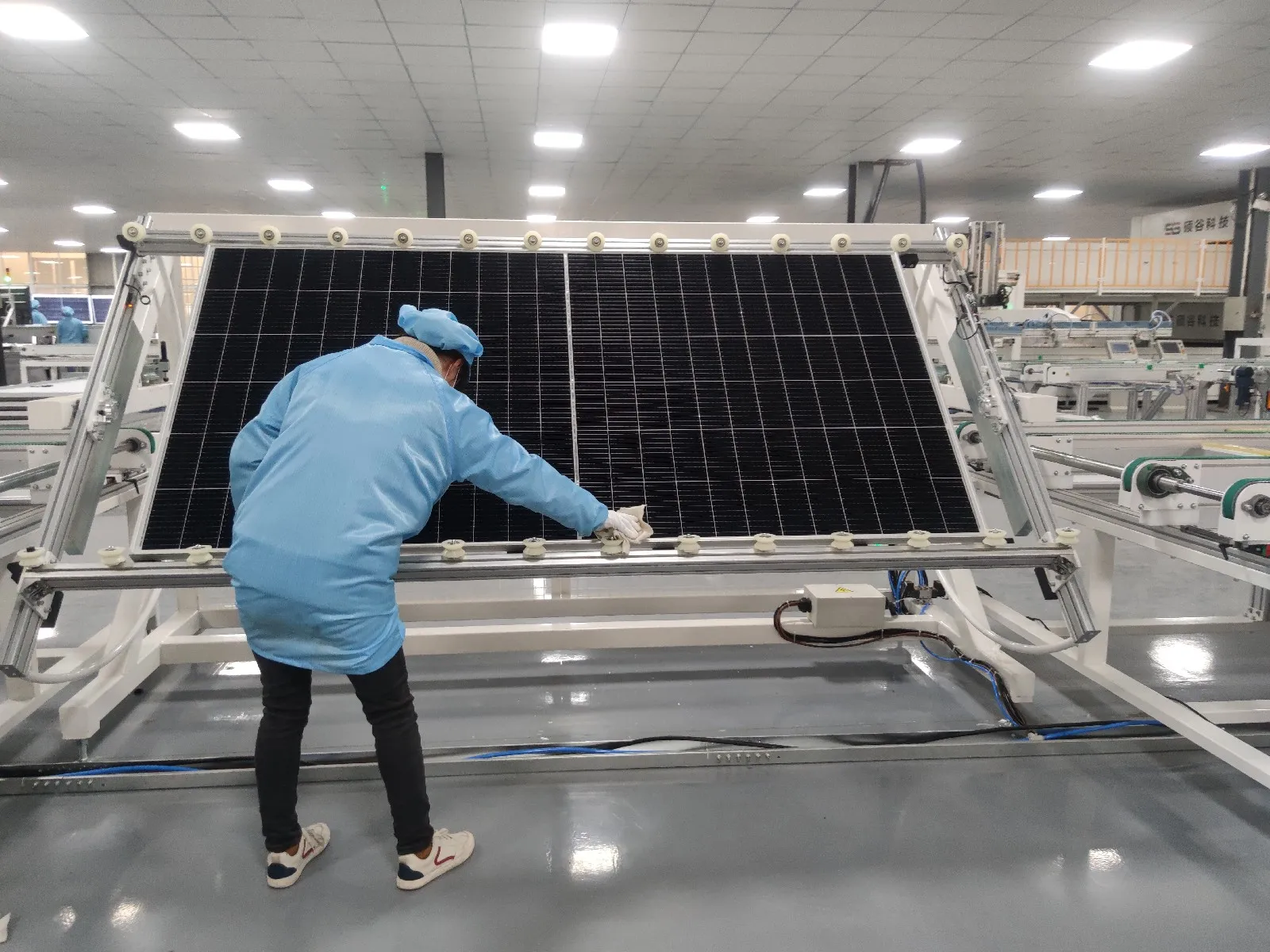
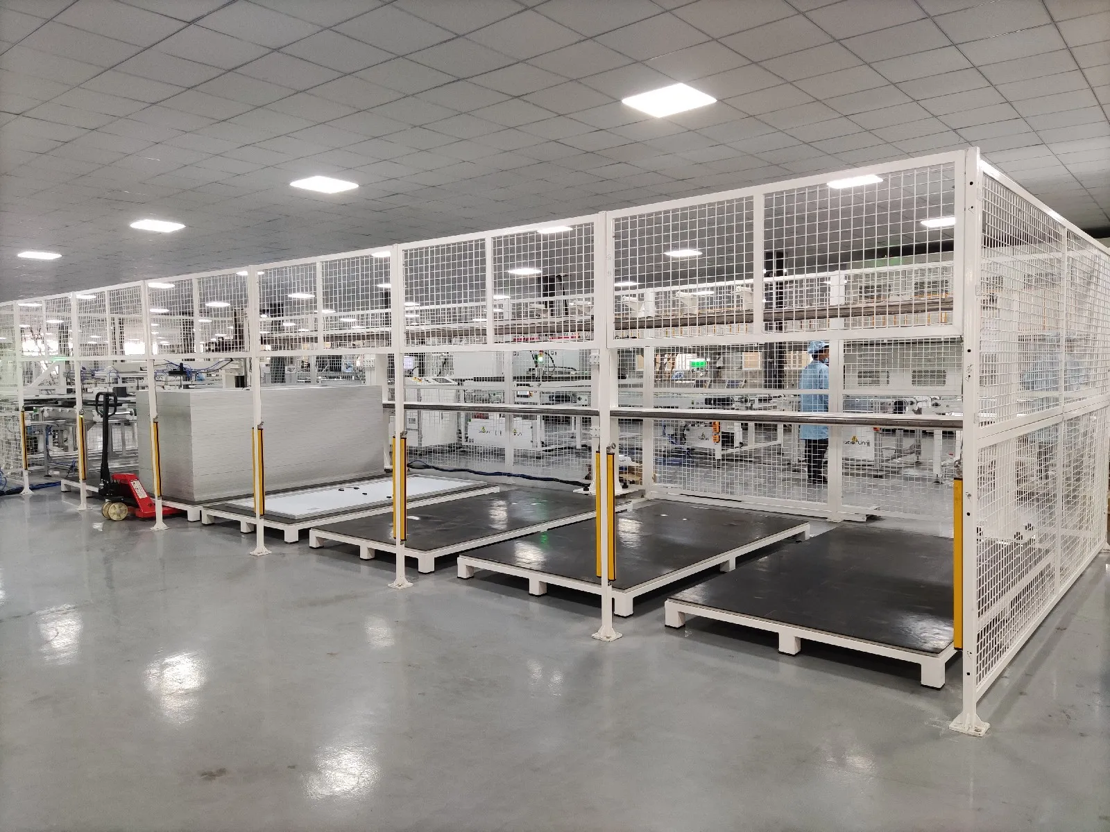
After the panel passes electrical, safety, EL and visual inspection, the factory prints its product label and records the final test results.
Each module normally receives a unique serial number. On an automatic line, this number can be connected to a MES or traceability system.
The factory can then trace a finished module back to information such as:
Solar cell batch
Stringer production data
EL images
Layup station
Laminator recipe
Framing station
I-V test result
Safety test result
Production date and shift
The finished modules are sorted by power class, stacked with protective materials and packed for transportation.
Packaging may seem like a simple process, but incorrect stacking or insufficient protection can damage good modules before they reach the project site.
Semi-Automatic or Fully Automatic?
A solar panel factory does not always need full automation.
Semi-automatic lines are often suitable for pilot projects, regional manufacturers and factories with lower planned capacity. Operators may handle bussing, material preparation, trimming, junction box installation and visual inspection manually.
Fully automatic lines add robotic handling, automatic conveyors, integrated inspection systems, production buffers and data traceability. They provide higher throughput and more consistent process control, but they also require stronger maintenance capability and better production management.
The correct level of automation depends on:
Planned annual capacity
Module design
Cell technology
Available investment
Local labor conditions
Product quality requirements
Future expansion plans
Do Not Choose Each Machine Separately
The biggest machine is not always the most important machine, and the fastest machine does not automatically create the fastest production line.
Capacity must be balanced across cell cutting, stringing, layup, bussing, lamination, framing, junction box installation and final testing.
The factory also needs supporting systems such as:
Automatic conveyors
Production buffers
Air compressors
Vacuum systems
Chillers
Material storage
MES and traceability software
Maintenance space
Quality-control areas
The module design must be confirmed before selecting the equipment. A line designed for conventional PERC full-cell modules may not be suitable for large-format TOPCon half-cells, HJT modules, BC cells or heavy glass-glass panels without changing several machines.
A realistic factory plan should therefore begin with the target module specification and annual production capacity. The final machine list comes after that.
Our view is simple: a reliable solar factory is not a pile of impressive machines but one balanced production system, and Ooitech can provide complete 5 MW to 1.2 GW semi-automatic and fully automatic solar panel production lines, factory layout design, installation, training, raw-material support and global after-sales service.
Related reading: what drives solar panel manufacturing machine price, what a solar panel manufacturing plant cost covers beyond the equipment, and how to start a solar panel manufacturing business.
Related: Solar Panel Manufacturing Machine: Stations and Layout explains how the same process sequence is re-sized from 5 MW to 1.2 GW and which inputs to freeze before ordering.
Related: Auto Solar Panel Junction Box Assembling Line: Stations covers the five machine groups, the ~1,000 pcs/h rating and the utilities that decide the layout.