Solar Panel Hot Spots: Why Temperature Matters
Table of Contents
Quick answer: A hot spot forms when a cell in a module is forced into reverse bias by shading, mismatch or a crack, and dissipates the power the rest of the string is producing as heat. The temperature it reaches is what decides whether it is an inconvenience or a warranty claim: heat concentrated in one cell can climb toward 160 °C while the surrounding module sits near 90 °C. The heat then attacks the materials in a fixed order — encapsulant first, then backsheet, then the glass and the interconnect joints. Bypass diodes exist to limit this by giving the current a low-resistance path around the affected cell group, which is why diode failure is the real hazard: a shaded cell is recoverable, a module with a failed bypass diode is not. What matters in practice is whether the diode conducts before the cell temperature reaches the damage threshold.
Partial shading is unavoidable in real installations. What decides whether it becomes a warranty claim is not the shading itself but the temperature it produces inside a cell, and how long the module materials are asked to survive it.
PV Module Reliability · Hot Spots and Safety · by Jerry, Ooitech
1. What a Hot Spot Is, in One Paragraph
Cells in a module are connected in series, so the same current has to pass through all of them. When one cell is shaded, its own photocurrent falls, but the string still pushes current through it. The shaded cell is driven into reverse bias and stops generating: it becomes a load. The power it dissipates is approximately the reverse voltage across it multiplied by the mismatch current flowing through it.
Because that power is concentrated in one cell rather than spread across the module, the local temperature rises. That local rise is the hot spot, and it is a materials problem before it is an electrical one.
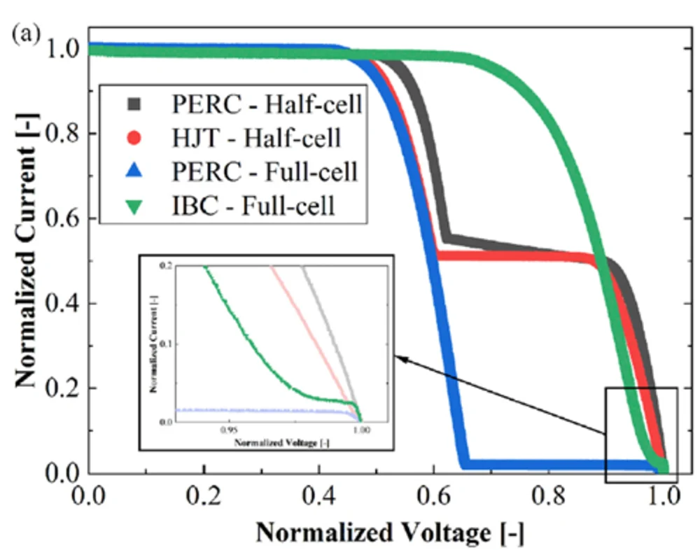
Fig. 1: Normalised I-V curves for PERC, HJT and IBC cells under partial shading. The curves diverge sharply once the shaded cell is driven into reverse bias, which is the region where the dissipated power — and therefore the hot-spot temperature — is decided.
2. Temperature Is the Design Margin
Two modules can lose the same amount of power under the same shadow and carry very different risk, because the damage is done by temperature rather than by watts. A shaded cell dissipating its mismatch power at 90 °C is a manageable condition. The same cell at 160 °C is accelerating every material around it.
| Condition | Typical hot-spot temperature | Interpretation |
|---|---|---|
| Well-designed cell with distributed reverse conduction | Around 90 °C reported in some designs | Comfortably inside the thermal budget of standard encapsulant and backsheet |
| Typical BC module | Often held below about 120 °C | Meaningful margin retained |
| Conventional cell, concentrated reverse breakdown | 160 °C and above | Materials are being consumed; lifetime and safety margin both fall |
These are indicative figures, not guarantees. Actual hot-spot temperature depends on the shaded area, ambient temperature, wind speed, module encapsulation, glass size, cell design and the test method used. The point of the table is the direction of travel, not the exact numbers: lower temperature is a larger safety margin, and a larger safety margin is what separates an inconvenience from a failure.
3. What the Heat Actually Damages
A hot spot is a localised thermal event, and each material in the stack has its own vulnerability.
| Component | What elevated temperature does |
|---|---|
| Encapsulant (EVA / POE) | Accelerates ageing and yellowing, and drives the decomposition reactions that release the volatiles responsible for delamination. Long-term exposure shortens the effective lifetime of the layer that holds the module together. |
| Backsheet | Polymeric backsheets degrade under sustained heat; cracking and chalking eventually compromise the dielectric barrier, which is a safety issue rather than only a performance one. |
| Glass | Local temperature gradients create differential expansion. In tempered and semi-tempered glass this adds stress to a material that is already under internal stress, and local hot spots are one of the contributing conditions behind spontaneous breakage. |
| Solder joints and ribbons | Repeated thermal cycling fatigues interconnects, raising series resistance. The damage accumulates: each shading event leaves the joint slightly worse than before. |
| Bypass diode and junction box | Every time a substring is bypassed, the diode carries the full string current and heats up. Repeated activation degrades the diode and the potting around it, and a failed diode removes the protection from that substring entirely. |
| The shaded cell itself | Reverse breakdown concentrated at weak points can permanently damage the junction, creating a defect that persists after the shadow has moved. |
Read the table as a list of warranty exposures rather than a physics lecture. Encapsulant ageing and backsheet degradation show up as power loss years later. Glass breakage shows up immediately. Solder fatigue shows up as gradually rising series resistance. None of them are repaired by removing the shadow afterwards.
4. Why Cell Architecture Changes the Temperature
The reason two cells can sit at very different temperatures under identical shading comes down to how their reverse current is distributed.
In a conventional cell, reverse breakdown tends to concentrate at local weak points: defect sites, cell edges, metallisation irregularities, micro-cracks, contaminated areas or regions of weaker passivation. Concentrating the same power into a small area produces a high local power density, and the temperature climbs quickly. The analogy is heating a metal plate versus heating a needle point with the same energy: the point gets hotter.
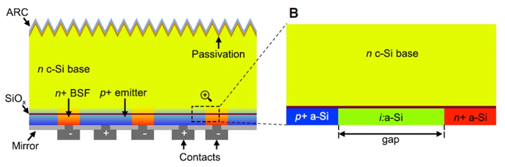
Fig. 2: A back-contact cell cross-section, with the gap between opposite-polarity regions marked. That gap, and the density of interleaved p and n regions across the rear, determine how evenly reverse current can spread and therefore how low the local temperature stays.
A back-contact cell inverts that. Its rear carries a large number of interleaved p and n regions, which from a circuit point of view behaves less like one large diode and more like many small diodes in parallel. When the cell is driven into reverse bias, conduction can spread across many of those distributed junctions rather than concentrating at a single weak point. Local power density falls, and so does the temperature.
The second factor is the reverse breakdown voltage itself. Since dissipated power scales with reverse voltage, a structure that clamps the reverse voltage at a lower level dissipates less. This is unusual in the sense that a low breakdown voltage, normally a weakness, becomes a protective mechanism under shading. The full electrical reasoning, including the mismatch current and bypass diode activation conditions, is set out in why BC solar cells handle shading better.
One clarification matters here, because it is widely misunderstood: better hot-spot behaviour is not the same as immunity to shading. Every cell loses output when shaded. If the shaded area in a substring becomes large enough, or several cells are fully shaded, the external bypass diode will activate and bypass the entire substring — including the unshaded cells in it. Under heavy shading, the advantage largely disappears. What BC architecture buys is better behaviour in the partial, localised shading that real rooftops actually produce.
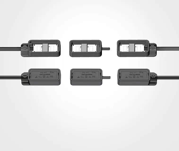
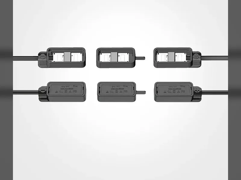
Fig. 3: A junction box opened to show its bypass diodes. These are passive devices: they conduct only when the substring voltage across them goes sufficiently negative. They are the last line of defence, and they only engage once the cell-level behaviour has already failed to hold the voltage down.
5. Where Hot-Spot Risk Is Highest
Hot spots are a function of shading, and shading is a function of installation. Some configurations produce partial shading as a routine condition rather than an occasional event.
| Application | Why hot-spot risk is elevated |
|---|---|
| Residential rooftops | Chimneys, dormers, vents and surrounding trees cast moving shadows that change through the day and the year. |
| Commercial and industrial rooftops | HVAC units, parapets and access walkways create fixed, permanent partial shading that cannot be designed away entirely. |
| Balcony and facade PV | Small arrays in constrained space, frequently shaded by railings, neighbouring structures and the building itself. |
| BIPV and multi-orientation arrays | Panels at different orientations within one system can shade each other, and non-uniform orientation makes string-level mismatch permanent. |
| Utility-scale ground mount | Generally the least shaded, but tracker rows, perimeter fencing and soiling bands still create localised effects. |
This is why hot-spot performance matters more in distributed generation than the headline efficiency figure suggests. A module on an open field spends most of its life under uniform irradiance. A module on a domestic roof may be partially shaded every afternoon for years.
6. Reducing the Risk in Practice
Five measures, roughly in order of how much control you have over them.
- Select cell architecture for the application, not just for efficiency. Where partial shading is a design condition rather than an exception, the ability to hold a lower hot-spot temperature is a specification item in its own right.
- Check the bypass diode configuration. More substrings means smaller bypassed sections when a diode activates, but it also means more diodes and more connections. The module's junction box arrangement is part of hot-spot behaviour, as described on our solar junction box page.
- Design the layout around the fixed shadows. Chimneys, poles, parapets and HVAC equipment cast predictable shadows. Positioning strings to reduce the number of affected substrings is cheaper than any module upgrade.
- Keep the array clean. Bird droppings, leaves, snow pockets and soiling bands are small-area, high-consequence shading events. A single dropping on one cell is exactly the condition that produces the worst local temperature.
- Inspect thermally. Hot spots are visible in infrared long before they become visible to the eye. The method is covered in thermal imaging for solar panels.
FAQ
What is a hot spot on a solar panel?
It is a localised high-temperature region in a cell caused by partial shading. The shaded cell is forced into reverse bias by the rest of the series string, stops generating and instead dissipates power, which raises its temperature above the surrounding cells.
How hot can a solar panel hot spot get?
It varies widely with shaded area, ambient temperature, wind speed, encapsulation and cell design. Reported figures range from around 90 °C for architectures with well-distributed reverse conduction, to 160 °C and above for cells where reverse breakdown concentrates at local weak points. The direction matters more than any single number.
Does a hot spot permanently damage a module?
It can. Sustained elevated temperature accelerates encapsulant ageing and backsheet degradation, fatigues solder joints, stresses the glass and can permanently damage the junction of the affected cell. Because the damage accumulates, repeated shading events are more consequential than a single event.
Are BC modules immune to shading?
No. Every cell loses output when shaded, and under heavy shading the external bypass diode activates and bypasses the whole substring regardless of cell architecture. What BC architecture improves is the behaviour under partial, localised shading: lower reverse voltage, more evenly distributed reverse current, and therefore a lower hot-spot temperature.
When does the bypass diode take over?
When the total reverse voltage across the shaded cells in a substring exceeds the combined forward voltage of the remaining unshaded cells plus the diode's own forward drop. Until that point the module relies on the cells' own reverse behaviour. Once the diode conducts, the whole substring — shaded and unshaded cells alike — is bypassed and stops contributing.
How do I know if my array has hot spots?
Infrared inspection is the practical method. A hot spot appears as a distinct warm area against the surrounding cells long before it produces any visible damage. Periodic thermal surveys under load, combined with a look at the I-V curve for unexpected series resistance growth, catch most developing problems.
Which is more important, hot-spot temperature or module efficiency?
They are not alternatives, and the right answer depends on the installation. On an open field with uniform irradiance, efficiency dominates. On a shaded domestic roof or a constrained balcony array, a module that holds a lower hot-spot temperature will typically have a better lifetime outcome and a lower warranty exposure than one that simply has the higher peak rating.
Final Thoughts
Shading cannot be designed out of most distributed installations, so the practical question is not whether a module will experience partial shading but how it behaves when it does. Hot-spot temperature is the variable that determines whether that experience costs you some generation or costs you the module, because temperature is what ages encapsulant, degrades backsheet, stresses glass and fatigues interconnects. When you specify modules for a roof with fixed obstructions, treat hot-spot behaviour as a performance and safety specification rather than a footnote to the datasheet. If you are planning a line for modules destined for shaded distributed applications, tell us the target market and module format and we will work through what the cell and junction box specification should cover.