Solar Panel Laminator: The Heart of PV Module Encapsulation
Product Introduction
As a key piece of equipment on the PV module encapsulation line, the laminator carries the heavy responsibility of fusing the laid-up materials into a single unit. Under set temperature, vacuum and pressure conditions, it heat-presses and bonds the prepared cells, busbars and encapsulant films together. The core objectives of this process include:
Air Removal: With the help of a vacuum environment, all air trapped between the layers is thoroughly removed to prevent internal bubbles and delamination.
Melt Bonding: Heating causes the EVA (or POE, etc.) film to melt and flow, making it easier to draw out air.
Pressure Application: While the film is molten, uniform pressure is used to fully fill the gaps between cells, ribbons, glass and backsheet.
Crosslinking & Curing: Holding sufficient time at high temperature drives the EVA to complete its crosslinking reaction, forming a stable, transparent solid layer with high bonding strength.
Integral Forming: Finally, the glass, cells, film and backsheet are tightly bonded into a sealed, robust and weather-resistant PV module.
Technical Parameters
The Laminator's Critical Position on the Production Line
Before looking at numbers, it helps to understand why this station matters so much. Lamination quality directly relates to the module's long-term reliability (PID resistance, damp-heat endurance, UV and mechanical load capability) and service life of over 25 years. The lamination cycle is also relatively long (typically 8-15 minutes per cycle), so equipment efficiency and stability have a decisive influence on whole-line capacity. Initial investment, running energy consumption and periodic maintenance all form an important part of module production cost.
| Parameter | Typical Specification |
|---|---|
| Lamination cycle time | 8-15 min per cycle |
| Temperature control accuracy | ±1-2°C |
| Chamber 1 temperature | approx. 110-120°C |
| Chamber 2 temperature | 140-150°C |
| Working / main vacuum level | 40-100 Pa (or lower) |
| Chamber 1 vacuum time | 300-400 s |
| Chamber 2 vacuum time | approx. 50-120 s |
| Chamber 2 holding time | approx. 400-600 s |
| Cooling target temperature | below 50°C |
| Heating method | Oil heating / Electric heating |
| Pressure method | Air bag / Diaphragm (silicone membrane) |
| Chamber structure | Double-deck three-chamber / double-chamber |
| Silicone sheet service life | 6000-8000 cycles |
Technical Advantages
Main Equipment Systems and Working Principle

A laminator usually integrates several core systems working together:
Heating System: Provides a precisely controllable heat field to melt the EVA and achieve crosslinking. Mainstream options include oil heating (thermal-oil circulation, uniform and stable temperature, high control accuracy, slightly more complex system) and electric heating (fast heating, simple structure, uniformity needs optimization). Control accuracy must be very high (commonly ±1-2°C), and temperature uniformity has a major impact on lamination quality.
Vacuum System: Builds and maintains the vacuum during lamination, drawing out interlayer air and gases generated by molten EVA. It typically contains a vacuum pump set (such as a Roots pump with rotary-vane or dry pumps), vacuum piping, valves and a vacuum gauge. Ultimate vacuum level (often 40-100 Pa), pumping speed and pressure-holding stability are all critical.
Pressure System: Applies uniform, controllable pressure to the stack under vacuum to promote the flow and filling of molten EVA. The air-bag / diaphragm type is widely used: compressed air (or nitrogen) is charged into a rubber bag or silicone diaphragm, transmitting pressure through flexible media such as a silicone plate, giving good uniformity and adaptability to different thicknesses. Key parameters are pressure value, pressurization speed, holding time and pressure uniformity.

Chamber and Main Structure: Forms the sealed space to maintain the vacuum and pressure environment. The current mainstream is a double-deck three-chamber or double-deck double-chamber structure. In the three-chamber design, one chamber runs at a relatively lower temperature with a longer vacuum time, focused on removing bubbles; the second runs hotter with slightly higher pressure to ensure the film fully crosslinks. The structure consists of a sturdy steel frame, liftable upper lid, fixed lower chamber, sealing strips and insulation, with sealing performance as the core metric.
Conveying System: Feeds the modules to be pressed into the chamber and sends finished products out. Roller or chain-plate conveying is common and must connect smoothly with upstream and downstream equipment such as edge sealing and trimming.
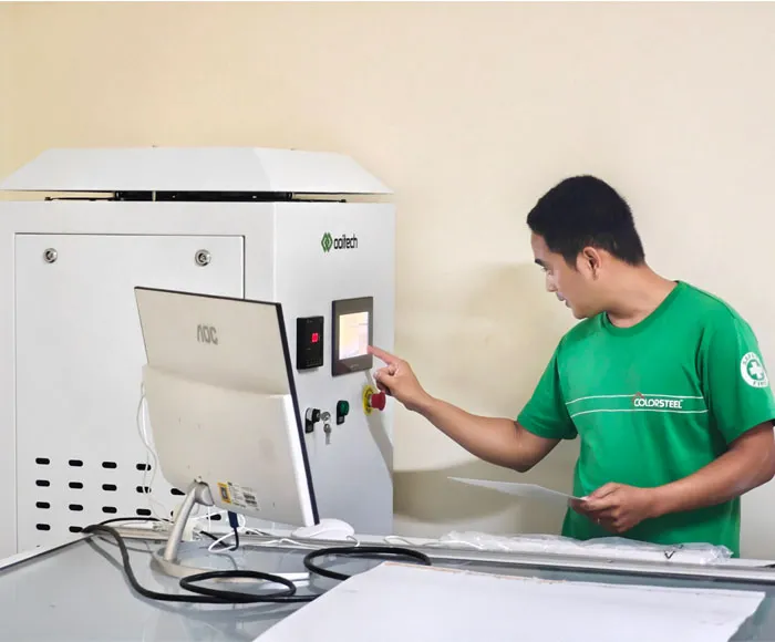
Control System: Acts as the equipment's brain, precisely controlling the whole lamination cycle (temperature, vacuum, pressure, time) for automated operation, parameter setting, data logging and fault diagnosis. It is based on a PLC and HMI touchscreen, with high-end units possibly integrating an MES interface.
Typical Lamination Process Steps (Air-Bag Type Example)
Loading: The laid-up module is conveyed into the opened first chamber.
Lid Closing: The upper lid descends, closes with the lower chamber and presses the sealing strip.
Vacuuming: The vacuum pump starts, quickly extracting chamber air to the set vacuum level (chamber 1 vacuum time usually 300-400 s) and removing most gas from the module.
Heating & Melting: Chamber 1 holds about 110-120°C; the incoming module is passively heated and the film melts (synchronized with vacuuming).
Pressurizing: After vacuuming, the air bag/diaphragm is inflated, applying uniform pressure to the molten module through a silicone plate. Under combined pressure and vacuum, the EVA flows to fill voids and bubbles are expelled.
Holding Pressure & Vacuum: Maintained at set temperature, high vacuum and pressure for a period (usually 300-400 s) to fully remove bubbles.
Vacuum & Pressure Release: When time is up, air is slowly introduced and bag pressure released to prevent deformation or internal stress from sudden pressure change.
Lid Opening & Transfer to Chamber 2: The lid rises and the module is conveyed to chamber 2.
Chamber 2 Operation: Set at 140-150°C. As bubbles were removed in chamber 1, vacuum time is short (about 50-120 s) but holding time is longer (about 400-600 s) to ensure full crosslinking. After vacuum release and lid opening, the module enters the cooling chamber (chamber 3).
Cooling: Cooling water in the chamber 3 base plate lowers the module to a safe range (e.g. below 50°C) to stabilize the structure. Units without a third chamber often add air cooling at atmospheric pressure.
Unloading: The lid rises and the laminated module is sent to the next process such as trimming.
Product Application
Key Control Parameters of the Lamination Process
The laminator is applied as the central encapsulation station across virtually all crystalline-silicon and many thin-film module lines, and getting these parameters right is what makes it work in real production:
Temperature: Must match the EVA melting and crosslinking window. Too high causes yellowing and delamination; too low gives insufficient crosslinking and poor bonding. Usually set at 140-150°C (adjusted for EVA grade).
Vacuum: Insufficient initial and main vacuum is the main cause of bubbles and delamination. The main vacuum stage often requires 40-100 Pa or lower.
Pressure: Too little pressure causes incomplete filling and weak bonding; too much or too fast can cause cell micro-cracks or displacement.
Time: Vacuum time, pressure/vacuum holding (curing) time and cooling time all need precise control. Insufficient curing time directly lowers crosslinking degree.
Cooling Rate: Cooling too fast can cause internal stress concentration or warping.
Equipment Maintenance Essentials
Regular maintenance is key to safeguarding equipment performance and life:
Daily Checks: Vacuum, pressure and temperature uniformity testing, sealing strip inspection, cleaning and checking of the high-temperature cloth and silicone sheet (look for scratches and aging), conveying system lubrication and surface cleaning.
Periodic Servicing: Regularly change vacuum pump oil, clean or replace vacuum filters, check the heating system (oil circuit or heating tubes), calibrate temperature/pressure/vacuum sensors, check electrical connections and thoroughly clean the chamber.
Silicone Sheet Replacement: The silicone sheet is a wear part, usually replaced after 6000-8000 uses or when severely scratched, hardened or damaged, to protect pressure uniformity and module surface quality (replacement is also advised when switching between double-glass and single-glass modules to avoid backsheet dimples).
The laminator is undoubtedly the heart of PV module manufacturing; its performance directly determines encapsulation quality and long-term reliability. As PV technology evolves toward higher efficiency, larger sizes, thinner cells and double-glass structures, the laminator faces higher demands in temperature uniformity, vacuum performance, pressure control accuracy, and automation and intelligence.
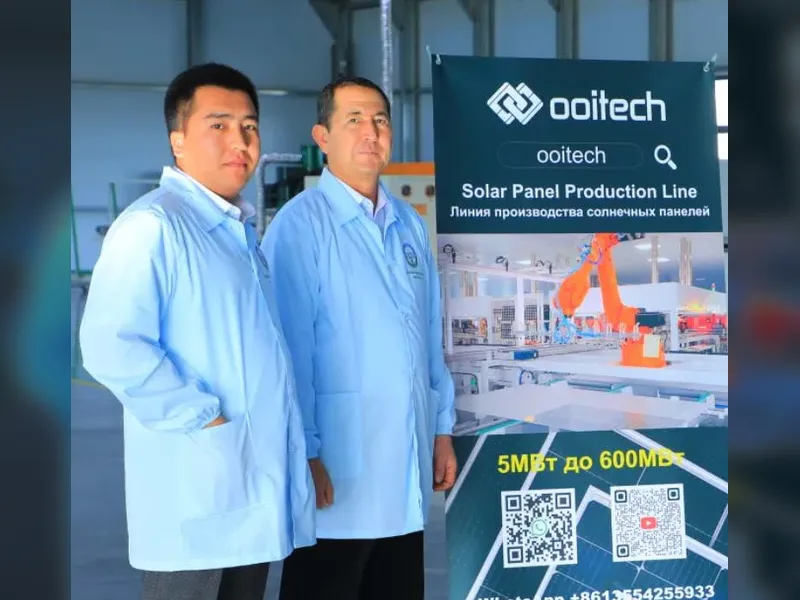
Ooitech's View
As a global solar panel production line supplier, Ooitech believes the laminator is where module reliability is truly won or lost: with thin wafers and double-glass designs now mainstream, the margin between good and poor temperature uniformity, vacuum stability and pressurization control has narrowed dramatically, and a well-matched three-chamber laminator is no longer a luxury but a baseline requirement. From our turnkey module-line experience, we find that pairing precise PLC-driven process recipes with disciplined silicone-sheet and seal maintenance does more for yield than chasing peak speed alone. For more real-world footage from solar module factories, you are welcome to follow and subscribe to the Ooitech YouTube channel at www.youtube.com/ooitech.