Editorial responsibility for this article rests with Wuhan Ooi Photoelectric Technology Co., Ltd. Written and reviewed by the Ooitech editorial team. See our editorial policy for how we write, where AI tools are used, and how to request a correction.
Three Kinds of PID in Solar Modules: Fingerprints and Causes
Table of Contents
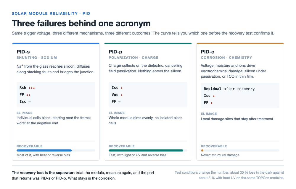
Quick answer: PID is one acronym on top of three failures with different physics and different remedies. Shunting, PID-s, is sodium from the glass reaching the silicon along crystal defects and bridging the junction: shunt resistance collapses, fill factor goes first, short-circuit current barely moves, and most of it can be recovered. Polarization, PID-p, keeps the charge inside the dielectric: field passivation is cancelled, current and voltage fall while fill factor holds, and light or reverse bias brings it back within days. Corrosion, PID-c, damages the material itself and does not come back. The practical separator is the recovery treatment, because whatever returns was reversible and the residue is not. Which one you meet is set by cell architecture, polarity to ground, encapsulation and moisture, and also by the lamp: one laboratory measured about 30 % loss on TOPCon modules in the dark against about 3 % with front ultraviolet illumination.
Two modules lose the same four percent. One recovers by morning; the other is scrap. The number on the report will not tell you which, and the remedy for the first does nothing for the second.
One acronym, three mechanisms
High voltage to ground is the entry ticket. What the cell does with that ticket depends on where the charge or the ion ends up: inside the silicon at a defect, on the surface of a dielectric, or in the chemistry of the material itself. The three are usually abbreviated PID-s for shunting, PID-p for polarization and PID-c for corrosion, and the single letter is carrying all of the meaning.
This matters commercially because the three have different projections. A polarization loss that looks alarming in a test report can recover on a roof in a week of daylight. A corrosion loss of the same magnitude is a warranty event. Reading "PID" as one number averages those two cases into a figure that predicts nothing.
PID-s: sodium finds the fault lines
Under negative bias to ground, sodium ions from the cover glass are driven through the encapsulant and the silicon nitride antireflection layer to the cell surface. The step that matters happens inside the silicon: sodium diffuses along stacking faults, planar defects in the crystal, and decorates them into conductive paths. A p-type cell has a very shallow n+ emitter front, a fraction of a micron, so those paths cross the junction easily. The result is a set of microscopic shorts in parallel with the diode.
Electrically the signature is distinctive. Shunt resistance drops hard, fill factor falls first, open-circuit voltage follows, and short-circuit current is nearly unchanged in the early stage. Because the leakage does not depend on irradiance, the loss shows up most in weak light, which is why the first complaint is usually about mornings, evenings and overcast days rather than about peak power. In an electroluminescence image the affected cells go dark or fully black, typically starting near the frame, and across a string the modules closest to the negative end are worst.
Most of it is recoverable. Remove the bias, add heat or apply reverse bias, and the sodium diffuses back out of the defects and the channels close. Inverter night-time recovery is built on exactly this. Deep cases leave a residue, which is worth remembering when somebody promises full restoration.
PID-p: nothing migrates inside the silicon
The efficient-cell era moved the dominant mechanism. In PID-p no ion enters the silicon; the fault is at the surface. High-efficiency cells carry aluminium oxide and silicon nitride films whose fixed charge creates a field that pushes minority carriers away from the surface, which is what field passivation is. Under a large voltage difference, external charge accumulates in or on those films. When its polarity opposes the fixed charge, the passivation is cancelled or inverted and carriers recombine at the surface again.
Three scenes produced this. Early n-type back-contact cells were the first place it was identified, around 2005, under positive bias to ground; the fix was positive grounding, and it is where the whole topic entered the industry. Bifacial PERC put the rear AlOx and SiNx passivation in direct contact with the encapsulant with no full-area aluminium behind it, so accumulated charge could cancel the negative fixed charge at the back. TOPCon cells behave similarly at the front, where a boron-diffused p+ emitter sits under the same dielectric stack, while the heavily doped polysilicon at the back is largely insensitive to surface charge.
The fingerprint is the mirror image of shunting: short-circuit current and open-circuit voltage fall, fill factor holds, shunt resistance stays flat, and the electroluminescence image dims uniformly instead of showing individual black cells. It is also fast. In accelerated testing, saturation arrives in hours to days, which is why the reported test duration tells you which mechanism the lab was chasing.
Recovery is quick and almost complete. Removing the bias is enough; reverse bias is faster. Light works too, and ultraviolet light particularly, because it raises the conductivity of the nitride so the accumulated charge can drain away.
PID-c: the one you cannot undo
Corrosion is the quiet one. With high voltage, moisture and ions together, electrochemical reactions attack the materials themselves. In crystalline modules the best-studied case is the rear of bifacial PERC, where silicon under the passivation is locally corroded and the passivation is structurally damaged. In thin-film modules the transparent conductive oxide corrodes and delaminates, which is where the name corrosion-type PID came from in the first place.
It develops slowly and often follows polarization: reversible charge accumulation first, irreversible chemistry later. Nothing removes it. Not removing the voltage, not light, not reverse bias. The practical consequence is that a recovery treatment doubles as a diagnostic, because the module tells you how much of its loss was never going to come back.
Reading the fingerprint
The three separate cleanly on a measured curve, provided the measurement is done properly, which brings its own problem a section later.
Same trigger, three mechanisms: the curve and the electroluminescence image narrow the diagnosis before the recovery test confirms it.
| Measurement | PID-s | PID-p |
|---|---|---|
| Short-circuit current | Nearly unchanged early | Falls |
| Open-circuit voltage | Falls | Falls |
| Fill factor | Falls clearly | Nearly unchanged |
| Shunt resistance | Collapses | Flat |
| Weak-light performance | Clearly worse | Relatively little change |
| Electroluminescence | Individual cells black, starting near the frame | Whole module dims evenly |
| Recovery | Mostly, given time, heat or reverse bias | Fast, with light or reverse bias |
Corrosion has no row of its own in that table because it is the residual: measure again after the recovery treatment and whatever did not return is PID-c, or material damage that will not heal. That is a crude instrument and it is the one that works in a service yard.
The lamp decides the number
Here is the finding that should change how you read a PID test report. Because light suppresses polarization, a test run in the dark overstates what happens outdoors. A national laboratory in the United States measured roughly 30 % power loss on TOPCon modules in dark conditions, and roughly 3 % when the front was illuminated with ultraviolet light during the test. Same modules, same voltage, an order of magnitude apart.
So a PID figure without test conditions is not a specification, it is a rumour. What a usable report states: whether the module was illuminated and with what spectrum, the chamber temperature and humidity, the bias voltage and its polarity relative to the module side, the duration, and which face was earthed. A vendor claiming "PID free" on the strength of a dark test has measured the worst case and called it the typical case. The relevant standard family, IEC 62804 for crystalline modules, allows both dark and illuminated routes, and the two do not produce comparable numbers.
The same caution applies inside the factory. A flash test at standard conditions tells you the module passed today; it says nothing about ion transport over twenty-five years. When a supplier shows a reliability test list, ask which items were run on modules and which on cells, and under what illumination.
Which one your bill of materials hands you
Cell architecture sets the ceiling, polarity sets the direction, and the packaging decides how easily ions and moisture move. The typical mapping looks like this.
| Cell or module type | Main type | Sensitive face | Sensitive polarity |
|---|---|---|---|
| P-type aluminium back surface field, single-sided PERC | PID-s | Front | Negative to ground |
| P-type bifacial PERC | PID-s plus PID-p or PID-c | Front and rear | Negative to ground |
| N-type TOPCon | PID-p dominant | Front | Mostly negative to ground |
| Early N-type IBC | PID-p | Front | Positive to ground |
| Thin film | PID-c | Transparent conductive oxide | Negative to ground |
Two caveats belong with that table. It describes typical literature cases, and within one technology route the film design and the encapsulation differ enough between manufacturers that the real answer is product-specific. And the polarity column is a system decision, not a module property: positive or negative grounding, floating arrays, and where the inverter sits relative to the string all shift the voltage each module sees against earth.
Three line decisions that move the odds
We build the machines, not the modules, so it is worth being precise about what a production line can and cannot influence here. It cannot ground your array. It can, however, decide three things that bound how much ionic traffic the packaging permits.
- Encapsulant choice and cure. Ionic conductivity through the encapsulant is the transport path for sodium and for the moisture that enables corrosion. Crosslink density after lamination is a process variable, and an under-cured sheet is a more permeable one. This is a lamination and material decision, made at the laminator and in the bill of materials, not at the tester.
- Edge sealing and frame interface. Moisture enters from the perimeter, which is also why shunting tends to appear near the frame first. Bead continuity, frame seating and trim quality are decided at framing and are visible in a cross-section.
- Glass specification. Sodium comes from the glass. Low-alkali or chemically strengthened cover glass changes the reservoir that feeds the mechanism, and that is a purchasing line in the BOM rather than a process setting.
None of those three is a PID test. Each one changes the exposure that a PID test would later measure, which is the honest way to describe what the line actually controls.
What the line should hand the field team
Here the factory has an advantage it usually does not use. A field diagnosis of PID depends on comparison: this string against that string, this module now against this module when it shipped. Without a shipping baseline at documented conditions, the comparison collapses into guesswork, and the recovery test loses the only reference that makes its result meaningful.
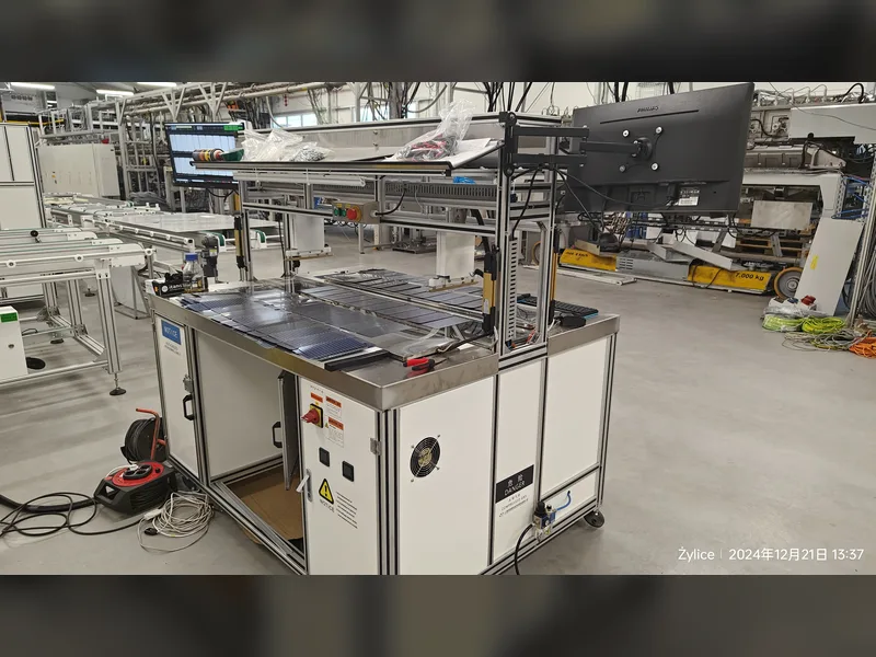
So the useful deliverable is not a pass stamp but a record: an electroluminescence image taken at a stated injection current and exposure, and a current-voltage curve taken at stated irradiance and temperature, both tied to the module serial. The image matters more than its name suggests: it shows you where it is dark, not why. That is a routine output of an EL and VI tester and of an A-class module IV tester, and it costs nothing extra beyond storing it properly.
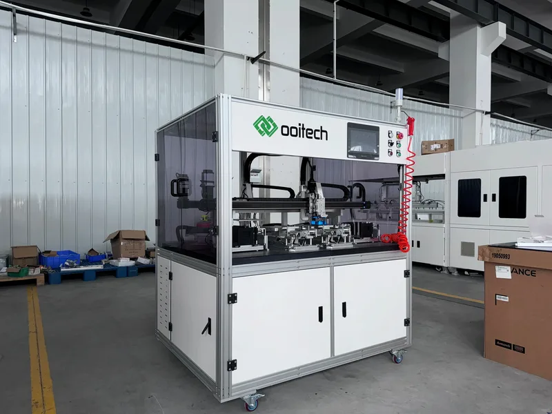
We record high-potential leakage and insulation resistance alongside the current-voltage curve and electroluminescence image under the module serial number, creating a verified electrical baseline before units ship to the field.
One boundary is worth stating plainly. The high-potential and ground-continuity tests on a production line verify electrical safety: dielectric withstand, insulation resistance, protective earthing continuity. They do not predict PID. A module can pass every safety test and still shunt in year four, because the two questions are different. Treating a hipot pass as evidence about PID resistance is a category error, and it is a common one in factory acceptance documents.
We run dielectric withstand, insulation resistance, and ground continuity testing on every finished panel at the end of the line, keeping electrical safety verification separate from long-term durability evaluations.
A three-step field diagnosis
When a string underperforms, the sequence that separates the three mechanisms is short.
First, look at where the loss sits. PID scales with voltage to ground, so it concentrates at one end of a string, and the opposite end looks normal. If the loss is scattered at random, stop and look for something else before blaming PID. Second, read the curve rather than the power number: current and voltage down with a flat fill factor points to polarization, while a collapsing shunt resistance with fill factor leading the decline points to shunting. Third, and only third, run the recovery treatment. Take the module, expose it to light or apply reverse bias, measure again, and compare against the shipping baseline. What returns within a day or two was reversible. What remains is the part that will be argued about in a claim.
Where these numbers come from
The mechanism descriptions, the fingerprint table, the susceptibility mapping and the dark-versus-illuminated comparison come from a Chinese-language technical article on the three PID mechanisms, the second instalment of a series by the same publisher, which attributes the 30 % and 3 % figures to a United States national laboratory study on TOPCon modules and the 2005 back-contact case to the manufacturer that reported it. The article’s own note applies to the table above: within one technology route, film design and encapsulation vary enough between manufacturers that the specific product must be measured rather than inferred. We build production equipment and testers; we have not run a PID chamber test for this article, and the encapsulation, framing and tester observations are process reasoning from our own machines, marked as such.
Frequently asked questions
Is PID one failure or three?
Three, with a shared trigger. Voltage to ground gets the process started; what happens next depends on whether sodium reaches the junction, whether charge accumulates on a dielectric, or whether the materials corrode. The remedies differ, and one of the three is irreversible.
How do I tell PID-s from PID-p without a laboratory?
Read the curve. Shunting takes shunt resistance and fill factor down while short-circuit current holds; polarization takes current and voltage down with fill factor nearly flat. Then confirm with a recovery treatment, since polarization returns quickly and shunting returns slowly and incompletely.
Why does the same module test 30 % down in the dark and 3 % down under light?
Because light raises the conductivity of the passivation layer, so accumulated charge drains away and the polarization cannot build. A dark test measures the worst case. The number is only meaningful with the illumination conditions attached.
Which cell technologies are most exposed?
P-type cells are the classic shunting case. Bifacial PERC can see shunting, polarization and corrosion depending on the side. TOPCon is mostly a front-side polarization story. Early back-contact cells polarized under positive bias, and thin film corrodes at the transparent oxide.
Can a production line prevent PID?
It can bound the exposure by controlling encapsulant cure, edge sealing and glass specification, and it can record the baseline that makes a field diagnosis possible. It cannot test twenty-five years, and it does not decide array grounding.
Does a hipot test prove anything about PID?
No. Hipot and ground-continuity tests verify electrical safety. PID is an ion and charge transport question over time. Passing one says nothing about the other, and the two are often confused in acceptance documents.
What should a PID test report contain?
Illumination and spectrum, chamber temperature and humidity, bias voltage and polarity, which face was earthed, and duration. Without those five, the percentage is not comparable to any other result, including the supplier’s own earlier data.
Is corrosion-type PID really irreversible?
Yes. It is structural damage to the material, so no recovery procedure restores it. That is why the recovery test is useful: it separates the recoverable part of a loss from the part that stays.
Final thoughts
The useful question is not whether a module has PID but which one it has, because only two of the three respond to anything you can do. Voltage to ground supplies the trigger, the cell and the packaging decide the mechanism, and the test lamp decides the number you read. A baseline recorded at known conditions is what turns a field argument into a measurement.
For production electrical verification, OOITech supplies the CHT9980A / CHT9981A PV safety comprehensive tester to measure hipot, insulation resistance, ground continuity, and wet leakage. Send your module stack, drawings, or laminate samples to our engineering team for testing evaluation.