DH1000 Damp Heat Test: Failure Modes and Mechanisms
Table of Contents
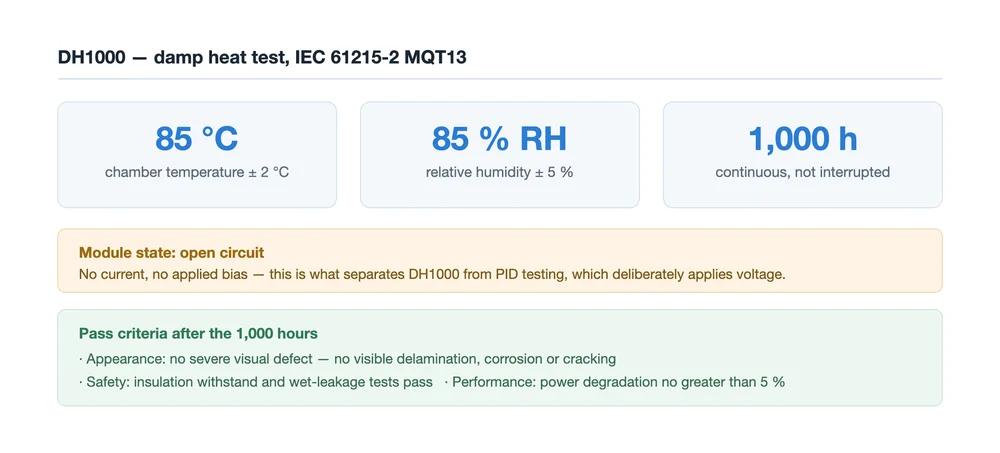
Quick answer: DH1000 is the damp heat test defined in IEC 61215-2 MQT13: 1,000 continuous hours at 85 °C ± 2 °C and 85 % RH ± 5 %, with the module held in open circuit. It passes only if appearance stays free of severe defects, insulation and wet-leakage tests pass, and power degradation stays within 5 %. What it really attacks is the moisture path into the module: the encapsulant and its interfaces, the edge seal, the cell metallisation and passivation, and the backsheet of single-glass modules. The characteristic electrical signature is fill factor falling with series resistance rising, while Isc barely moves.
Reading a DH1000 result is not about the pass mark. It is about which layer failed first, and whether the process that made it can be held.
The Conditions, and the One That Is Usually Missed
Temperature, humidity and duration are the three numbers everyone quotes. The fourth parameter is the one that changes how the test is interpreted: the module sits in open circuit. No current flows and no external bias is applied, so the failure has to come from the environment acting on the materials rather than from an electrically driven mechanism.
That is also what separates DH1000 from PID testing, where a voltage is applied deliberately to drive ion migration. If a module fails damp heat, the first question is therefore a materials question: where did the moisture get in, and what did it dissolve on the way.
The Conditions Did Not Change — the Pass Bar Did
The physical conditions of DH1000 have been stable for roughly two decades, and the 2021 revision of IEC 61215 still uses them. What changed is what the market accepts as evidence:
- Extended duration. Buyers and third-party laboratories increasingly specify doubled or tripled exposure — DH2000 or DH3000 — to separate reliability tiers, because a plain DH1000 pass stopped discriminating between established suppliers once glass-glass constructions became common.
- Technology sensitivity. The same test is harder on some cell generations than others. N-type cells are more sensitive to moisture and to weak acid environments, so damp heat results that were comfortable for P-type modules have become a real production constraint.
- Sequence testing. A single test cannot represent a field lifetime, so specifications now often require sequences such as thermal cycling followed by damp heat, PID plus damp heat, or damp heat plus mechanical load.
What DH1000 Actually Stresses
| Layer or interface | What the exposure tests | Typical weak point |
|---|---|---|
| Encapsulant film | Hydrolysis resistance and chemical stability under heat and humidity | EVA hydrolysing to acetic acid; POE and EPE are more stable but cost more |
| Bonded interfaces | Adhesion between glass, encapsulant, cell and backsheet | Moisture breaking the chemical bonds that hold the stack together |
| Edge seal | Water-vapour transmission through silicone, tape or butyl, and its adhesion to frame and glass | Edge ingress, which is why the failure often starts at the perimeter |
| Cell metallisation | Electrochemical corrosion resistance of the front and rear pastes | Silver-aluminium paste, where the two metals form a galvanic couple |
| Passivation layers | Stability of SiNx and Al₂O₃, and retention of the hydrogen they carry | Hydrolysis and dehydrogenation, which reopen interface defects |
| Backsheet (single-glass) | Barrier and weather resistance of the first moisture defence | Yellowing, embrittlement and cracking that let moisture through |
The Electrical Signature
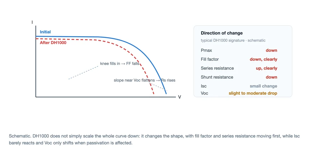
Damp heat does not scale the whole I-V curve down evenly. The shape changes, and it changes in a recognisable order: series resistance rises, fill factor falls, shunt resistance drops, Isc moves very little, and Voc shifts only slightly unless passivation has been damaged. Power loss is the contractual number, but fill factor and series resistance are the diagnostic ones — they tell you the loss is resistive and contact-related rather than optical.
This is the same pair of parameters that shop-floor fill factor monitoring uses to catch production defects before they are built into a module. A DH1000 result that moves FF and Rs is telling you the same story as a process drift: a contact or interface problem, not a shading or optical one. How far the numbers move depends on the bill of materials and the process window, so absolute values from one module cannot be transferred to another design.
The EL Signature
Electroluminescence turns the electrical story into an image, which is why it is the standard companion to a damp heat result:
- Dark edges. Moisture enters from the perimeter, so the outer ring of cells darkens first. A dark border in EL is the fingerprint of an edge-seal or encapsulant path.
- Finger darkening and breaks. Front fingers go dark and can break physically once contact corrosion has progressed. This is the visual counterpart of the rising series resistance.
- Visible changes in severe cases. Corrosion discolouration on busbars and fingers, delamination or bubbles at the encapsulant interface, and yellowing or embrittlement of the backsheet on single-glass modules.
Because the reading is comparative, the inspection setup matters as much as the image: an inline or offline EL configuration with a repeatable exposure and gain is what makes a before-and-after comparison defensible.
The Mechanism Chain
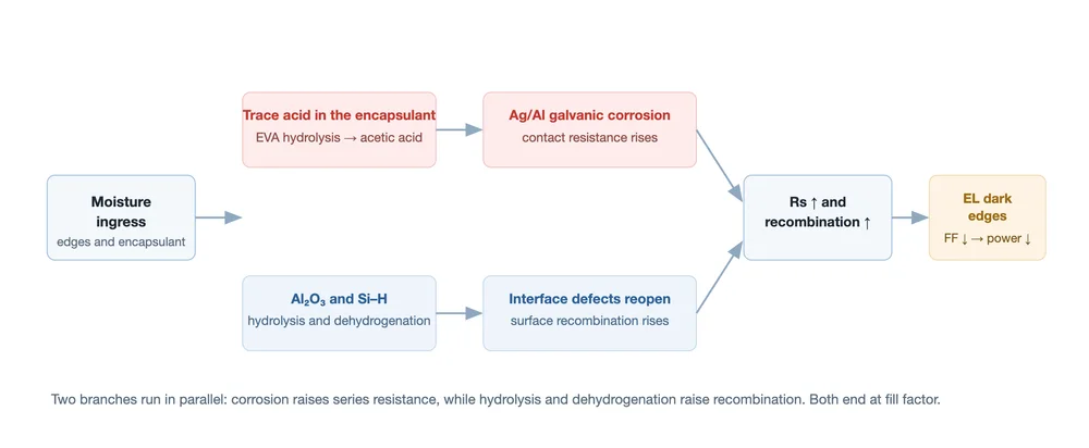
Put the sequence together and it reads as one chain with two parallel branches:
Moisture ingress → trace acid in the encapsulant → galvanic corrosion of the front paste → contact resistance up, and in parallel moisture ingress → hydrolysis of Al₂O₃ and loss of hydrogen → interface defects reopen → recombination up. Both branches converge on fill factor and end as power loss, and both are visible in EL as dark edges or dark cells.
Two amplifiers sit inside that chain. Ionic contamination — sodium from the glass, calcium, chloride and sulphur from handling, flux residues from assembly — forms an electrolyte that accelerates the corrosion. And encapsulant chemistry feeds the first branch: when EVA hydrolyses it produces acetic acid, which attacks the metal contact interfaces and the anti-reflective coating on the glass.
Why N-Type Cells Feel It More
On a boron-diffused emitter, the front metallisation is usually a silver-aluminium paste: aluminium is added to reach a good ohmic contact through the passivation stack. Silver and aluminium sit far apart in electrochemical potential, so once moisture and acid reach that interface the pair forms a local battery, and the aluminium side is consumed. That is why the damage concentrates at the contact rather than spreading evenly.
The front passivation is the second exposure. Aluminium oxide is effective as a passivation layer and sensitive to moisture; when it hydrolyses and the hydrogen stored in the silicon-hydrogen bonds is lost, the dangling bonds it was passivating come back, and surface recombination rises. Neither effect is visible in a visual inspection at the pass mark, which is why the electrical signature and the EL image are read together.
Where the Line Can Change the Outcome
A damp heat result is decided long before the chamber door closes. Four decisions dominate:
- Encapsulant chemistry. The choice between EVA and a polyolefin-based film such as POE or EPE trades cost against hydrolysis resistance. The encapsulant film comparison sets out where each one fits and what its peel strength means for the bonded interfaces.
- Lamination process window. Vacuum stage, temperature profile and time determine how completely the encapsulant crosslinks and how well the interfaces bond. A window that is comfortable on one film is not automatically right for another, as the work on vacuum pump behaviour and the EVA window shows.
- Residue and cleanliness control. Flux residues and handling contamination become the electrolyte in the chamber. Control at the stringing and bussing stations is cheaper than a corrective BOM change later.
- Backsheet and edge materials. On single-glass modules the backsheet is the first barrier, and the edge seal is the last one. Both are specified for water-vapour transmission rather than for appearance.
If a design fails damp heat, changing the chamber conditions is not one of the options. The choices are material, interface and process — and the sequence test that reproduces the field failure is the evidence that the change worked. The wider set of module and cell level tests is listed in PV module reliability tests.
FAQ
What exactly is DH1000?
A damp heat exposure of 1,000 continuous hours at 85 °C and 85 % relative humidity, defined in IEC 61215-2 MQT13, with the module in open circuit. It is a qualification test, not a lifetime prediction.
Why is the module tested in open circuit?
To test the materials rather than an electrically driven effect. With no bias applied, a failure has to come from moisture and heat acting on the encapsulant, the interfaces and the metallisation.
What fails first in a damp heat result?
In most cases the perimeter. Moisture takes the edge route, so EL shows dark edges before the centre of the module changes, and the electrical signature shows series resistance rising as contact corrosion starts.
Is DH1000 the same as PID testing?
No. PID testing deliberately applies a voltage to drive ion migration; DH1000 applies no bias and tests moisture-driven degradation. They are often run as a sequence, which is why the two are frequently confused in specifications.
Why do buyers ask for DH2000 or DH3000?
Because a DH1000 pass no longer differentiates between established suppliers. Doubling or tripling the exposure separates reliability tiers, particularly for glass-glass modules where the standard test is no longer a bottleneck.
Can damp heat results be checked in-house?
The electrical and EL sides can: IV measurement, fill factor tracking and electroluminescence inspection give a comparable before-and-after record. The chamber exposure itself is normally done by a qualified laboratory, and the sequence matters as much as the single test.
Final Thoughts
DH1000 is a materials test with an electrical readout: moisture finds the weakest interface, and the meter tells you where it went. Judge a result by which layer moved first — fill factor and series resistance for the contact path, Voc and EL for the passivation path — not by whether the module cleared five percent. If you are specifying for a humid site, ask for the sequence result and the EL images, not only the pass certificate.