EL Testing for Solar Panels: Inline vs Offline Setup
Table of Contents
EL Testing for Solar Panels: Inline vs Offline Setup
EL testing is the only inspection step that sees inside a finished module. Where you put the station decides which defects you catch while they are still cheap to fix: inline behind the stringer, offline on a glass stage, or at string level.
PV Module Manufacturing · Inspection & Quality Control · by Jerry, Ooitech
1. What EL Testing Actually Proves on a Module Line
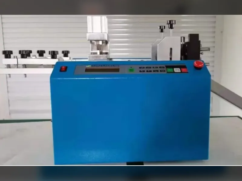
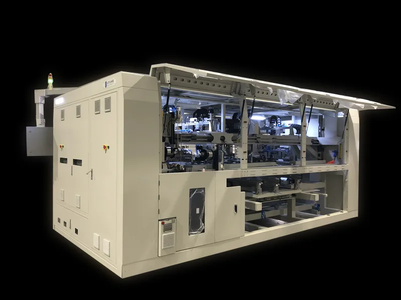
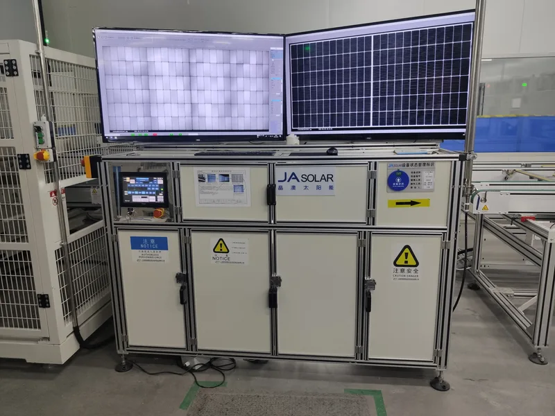
Fig. 1: A module-level EL inspection station. The left monitor shows the electroluminescence image; the right shows the module itself, so the operator can match a dark area to a physical cell.
Electroluminescence testing passes a forward current through the cells. A silicon cell that is intact emits infrared light in proportion to how well it conducts; a cracked, contaminated or badly soldered area emits less or nothing. An infrared camera images that emission, and the resulting EL image shows the internal state of every cell at once.
On a production line, that makes EL testing the main gate for six defect classes:
| Defect class | What it looks like in the EL image | Typical origin on the line |
|---|---|---|
| Crack | Dark lines or branches across a cell, often invisible under daylight | Stringing, handling, layup |
| Breakage | Missing or fully dark cell area, sharp edges | Mechanical impact, frame pressing |
| Black spot | Localised dark patches inside one cell | Wafer contamination, material defect |
| Mixed wafers | One cell visibly brighter or darker than its neighbours | Binning mix-up at the cell store |
| Process defect | Finger interruptions, uneven emission across a cell | Metallisation, printing, handling |
| Cold solder joint | Dark patch along a ribbon or at a pad | Soldering temperature or flux |
Two limits are worth understanding before you write a specification. EL testing does not measure power output. That is the job of an IV tester with a sun simulator, and the two machines answer different questions. Nor does EL testing see behind the aluminium frame or under the junction box, because the infrared emission is blocked there. Anything you need to inspect in those areas has to be checked before framing.
2. Inline, Offline or String Level: Where the Station Sits
There are three places an EL station can sit, and they are not interchangeable. Ooitech builds units for all three, and the technical data sheets describe the trade-off directly.
| Placement | Example model | How the module moves | Best fit when |
|---|---|---|---|
| Inline, automatic | OPT-M950B (8 cameras) | Three canvas conveyor belts, automatic omni-directional alignment, test cycle ≤20 s | Continuous flow, high volume, and you want inspection inside the takt time |
| Offline, semi-automatic | OEL-S2400 (2 cameras), OEL-CCD2400 (6 cameras) | Module placed by operator on a super-white tempered glass stage | Mixed batch sizes, rework loops, or a line where a 20 s station would become the bottleneck |
| String level | OPT-S110H | Cell string inspected before layup | You want to reject a bad string before encapsulant makes it permanent |
Placement decides what you catch, not how good the camera is.
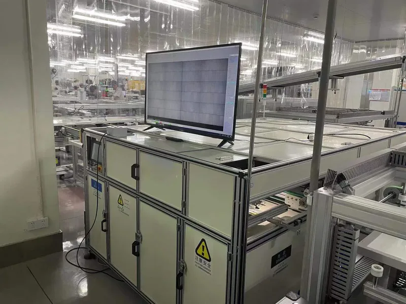
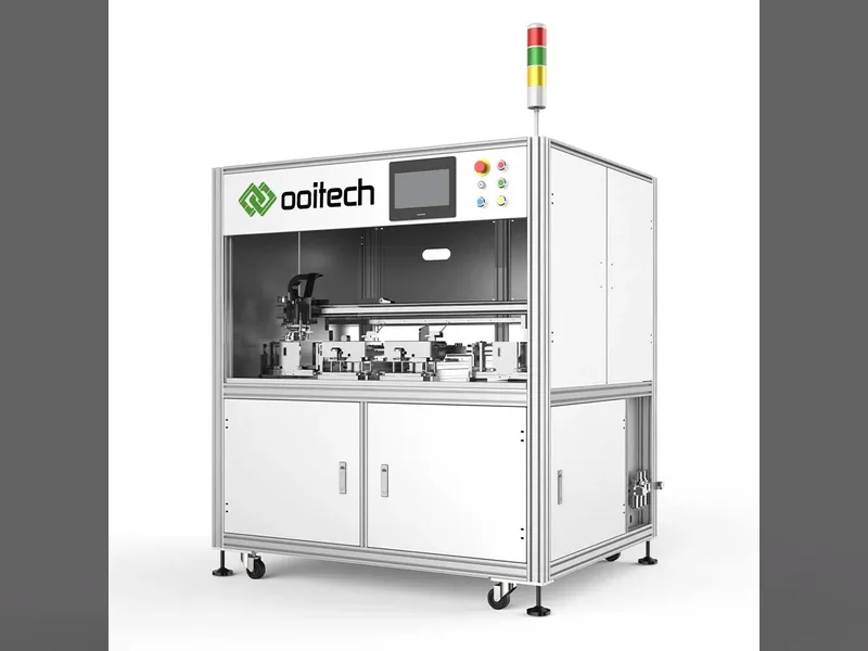
Fig. 2: An inline EL station inside a module clean room. The conveyor carries the module through the imaging position without operator handling, which is what keeps the test inside a 20-second cycle.
The offline units in Ooitech's range state the monitoring point as before or after laminating, and the automatic OPT-M950B is described as universal for before and after the layup. That flexibility matters more than it sounds: it lets one machine serve both an inline process check and a final quality gate, at the cost of the operator handling the module.
3. Camera Count, Resolution and Cycle Time
These three numbers are usually quoted as a specification list. In practice they are one decision: how small a defect you must be able to prove, at what production rate.
| Parameter | OEL-S2400 | OEL-CCD2400 | OPT-M950B |
|---|---|---|---|
| Cameras | 2 | 6 × 4 MP (24 MP total) | 8 (4 EL + 4 VI) |
| Resolution | 6000 × 4000 | 24 MP combined | 1920 × 1200 (EL), 5440 × 3648 (VI) |
| Imaging precision | Not specified | Not specified | 0.5 mm/pixel (EL), 0.1 mm/pixel (VI) |
| Max module size | ≤2500 × 1400 mm | ≤2600 × 1500 mm | Length 1650–2500 mm, width 992–1400 mm |
| Exposure time | 1–60 s | 1–60 s | 0.5–10 s, adjustable |
| Test cycle | Not specified | Not specified | ≤20 s per module |
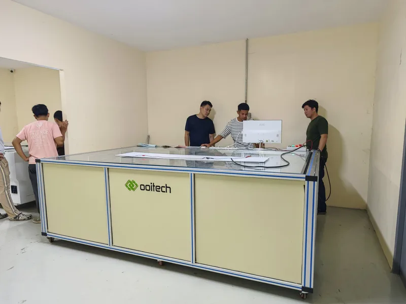
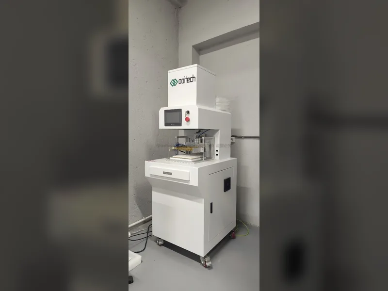
Fig. 3: An offline EL defect tester. The module is loaded onto a glass stage by the operator, so the station is not bound by line takt time. That suits rework loops and mixed batch sizes.
The OPT-M950B reaches its precision differently from the offline units. Four cameras image the module from above while the module indexes through three positions, and the software stitches the captures into one seamless image. That is why an 8-camera machine can keep a ≤20 s cycle while still holding 0.5 mm per pixel on the EL image and 0.1 mm per pixel on the visual image.
The practical question is not which machine has more cameras. It is: what is the smallest crack your customer's incoming inspection will find? Once you know that number in millimetres, the camera count and the placement follow from it. Buying 24 MP to detect a 5 mm crack is money spent on a capability you will never invoice.
4. Why the EL Image Sometimes Looks Wrong
This is the most common support topic in our own EL service history, and it is almost never a camera failure. When an EL image degrades, the cause is usually one of five settings or mechanical conditions. The usual symptoms are an image that is dark, washed out, uneven between cells, or missing part of the module.
| Symptom | Check first | Can it be corrected remotely? |
|---|---|---|
| Whole image too dark or too bright | Exposure time (units run 0.5–10 s or 1–60 s) and injected current | Usually yes: parameter change |
| One region missing or doubled | Module alignment before imaging; mosaic overlaps | Partly: alignment is mechanical, mosaic settings are not |
| Image correct after adjustment, then wrong again | Whether the recipe was saved for the current product, or only applied live | Yes: save the recipe per module type |
| Camera or CCD error after a restart | Camera cabling, and whether the illumination units behind the camera are lit | Diagnosis remotely; a dead lamp is on-site |
| Uniformly dark cells in one string | Current injection contact — the tooling must reach the bus bar properly | Partly: it depends on the tooling |
Two habits remove most of this class of problem. First, build a saved recipe for every module type you run, instead of adjusting live and moving on. The second and third shift will otherwise repeat the adjustment. Second, treat the illumination units as a consumable with a check interval: an LED that has dimmed on one side produces an image that looks like a process defect but is a lighting defect.
5. What to Send Before You Ask for a Quotation
EL tester sizing is driven by your module, not by your budget. An enquiry that includes the six items below can be answered with a specific model and a firm configuration; one that says only "we need an EL tester" cannot.
| What to send | Why it changes the machine |
|---|---|
| Module length and width, in mm | Defines the alignment envelope. A 60-cell 1650 × 992 mm module and a 72-cell 2500 × 1400 mm module do not fit the same station. |
| Cell technology: half-cell, double-glass, thin film | Determines current injection and tooling. Double-glass and thin film modules need different power-up arrangements. |
| Where the station sits: before or after lamination | Decides framing, handling and whether the bus bar is still accessible. |
| Line takt time, in seconds per module | Inline units must fit inside it. The OPT-M950B test cycle is ≤20 s; an offline unit is not bound by the line. |
| Smallest defect you must prove, in mm | Sets the required imaging precision, and therefore the camera configuration. |
| Facility data: power, air, space | The automatic unit draws AC220 V / 15 A, needs 0.6–0.8 MPa air, and occupies 2800 × 2260 × 1415 mm. Offline units are smaller but the 6-camera type draws 220 V / 20 A. |
One item is optional but worth deciding early: MES integration. The OPT-M950B saves each EL image under the module barcode and can upload it to your MES, with barcode query and date query in the software. If traceability is a customer requirement, say so at quotation stage rather than after installation.
6. Matching the EL Station to the Rest of the Line
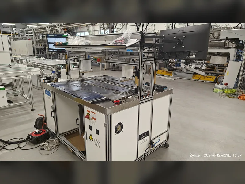
Fig. 4: String-level EL inspection catches a cracked or cold-soldered cell before encapsulant makes the defect permanent. It is the cheapest place on the line to find it.
An EL tester never runs alone. It sits between machines that determine whether it can do its job, and two of them matter more than the rest.
The stringer upstream. Most cracks that EL testing finds were created at stringing or at the handling step immediately after it. If your stringer produces cold solder joints or cell cracks at a steady rate, an EL tester will report them accurately and continuously, but it will not reduce them. Fixing the stringer is a separate project, and the EL data is what tells you whether the fix worked.
The IV tester downstream. EL and IV answer different questions, and a module can pass one and fail the other. A cracked cell may still deliver acceptable power at the flash test; a module with correct power can still contain a crack that will propagate in the field. Lines that run both generally place EL before or after lamination, and the IV curve measurement after framing and curing, so the two results can be compared per module barcode.
If your line is still being specified, the sequence decision is easier to make before the equipment list is frozen. Our overview of the machines on a solar panel line sets out where each inspection step normally sits.
7. FAQ
Can EL testing be built into the stringer, or does it need a separate station?
Some stringers offer an integrated EL option, and it inspects the string before layup. That catches cracked or poorly soldered cells early, but it cannot inspect the laminated module, because the module does not exist yet. If your quality gate is on the finished laminate, you still need a separate station. In practice many lines run string-level inspection and a module-level EL tester, and the two catch different things.
The EL image is not right. Can it be adjusted remotely?
Usually yes. Exposure time, injected current, gain, grey scale and mosaic parameters are software settings, and the automatic units expose high-current and low-current testing as selectable functions. Send the image, the barcode, the saved recipe and the current settings, and the adjustment can normally be made without a site visit. Mechanical problems are not remote fixes: module alignment, a lamp that is out, a damaged cable.
We adjusted the settings and now most images look wrong. What should we check?
Check whether the change was saved as a recipe for the current module type. Settings applied live are lost when the next product is loaded, and the following shift often re-adjusts from a different starting point. Build one saved recipe per module type, name it, and lock it.
After restarting the computer, both the CCD and the EL camera report an error. What now?
Two things to verify before calling support: that each camera cable is seated at both ends, and that the illumination units behind the cameras are lit. If one LED array is dead, the camera may still report an error and the image on that side will be dark. Report which cameras fail and whether the lamps are lit. That distinguishes a cabling fault from a lighting fault in one message.
What module sizes can an EL tester handle?
It depends on the model. The automatic OPT-M950B covers modules from 1650 to 2500 mm long and 992 to 1400 mm wide, which includes the common 60-cell 1650 × 992 mm and 72-cell 2500 × 1400 mm formats. The OEL-S2400 accepts up to 2500 × 1400 mm and the 6-camera OEL-CCD2400 up to 2600 × 1500 mm. Conventional, double-glass, thin-film and half-cell modules are all supported across the range.
Can one machine do both EL and visual inspection?
The automatic 8-camera OPT-M950B does. Four cameras image electroluminescence and four image in visible light, in the same pass, with the software mosaicing both. That gives you the internal defect image and the surface image from one handling cycle. The smaller offline units image EL only.
What is the smallest defect the machine can detect?
The OPT-M950B is specified at 0.5 mm per pixel on the EL image and 0.1 mm per pixel on the visual image. The practical detection limit is set by that pixel size plus the contrast of the defect against the surrounding cell, so a crack that crosses several pixels is reliable while a hairline that falls inside one pixel is not. This is why the smallest defect you must prove, in millimetres, should be stated in the enquiry, not inferred from the camera count.
Are the images traceable, and can they go to our MES?
Yes. The automatic unit recognises the module barcode, names and saves each EL image by that barcode, and supports MES interfacing. The software also provides barcode query and date query, so a module can be traced back to its image after shipment.
What are the installation requirements and the warranty terms?
The automatic OPT-M950B requires AC220 V / 15 A, 0.6–0.8 MPa compressed air, and an operating environment of +15 °C to +40 °C at 10–75% humidity; it occupies 2800 × 2260 × 1415 mm. The 6-camera offline unit draws 220 V / 50 Hz / 1 PH, 20 A. Warranty on the semi-automatic EL units is one year after successful installation or sixteen months from the bill of lading date, whichever comes first, with maintenance spare parts supplied free of charge during the period; consumables and spare-part courier costs are not included.
Final Thoughts
Decide where the EL station sits before you compare models, because placement determines which defects you can still fix cheaply. Then write down the smallest defect your customer's inspection will find, in millimetres, and let that number set the camera configuration. If you send us the module dimensions, cell technology, monitoring point, takt time and facility data, we will come back with a specific model and configuration rather than a general brochure.