Editorial responsibility for this article rests with Wuhan Ooi Photoelectric Technology Co., Ltd. Written and reviewed by the Ooitech editorial team. See our editorial policy for how we write, where AI tools are used, and how to request a correction.
BC Stringing Warp: Both Ends Curl, Five Levers to Fix It
Table of Contents
Quick answer: Back-contact cells leave the stringer flat in the middle and lifted at both ends because the heat arrives on one side only and the ends are not held. Unoptimised lines run 1.0–1.5 mm of end warp, and severe batches exceed 2 mm against a layup tolerance of ±0.5 mm. The fix is not a cooler iron: it is five levers set together — front preheat, end-zone tension, incoming warp binning, full-width hold-down, and separate recipes per wafer and ribbon spec.
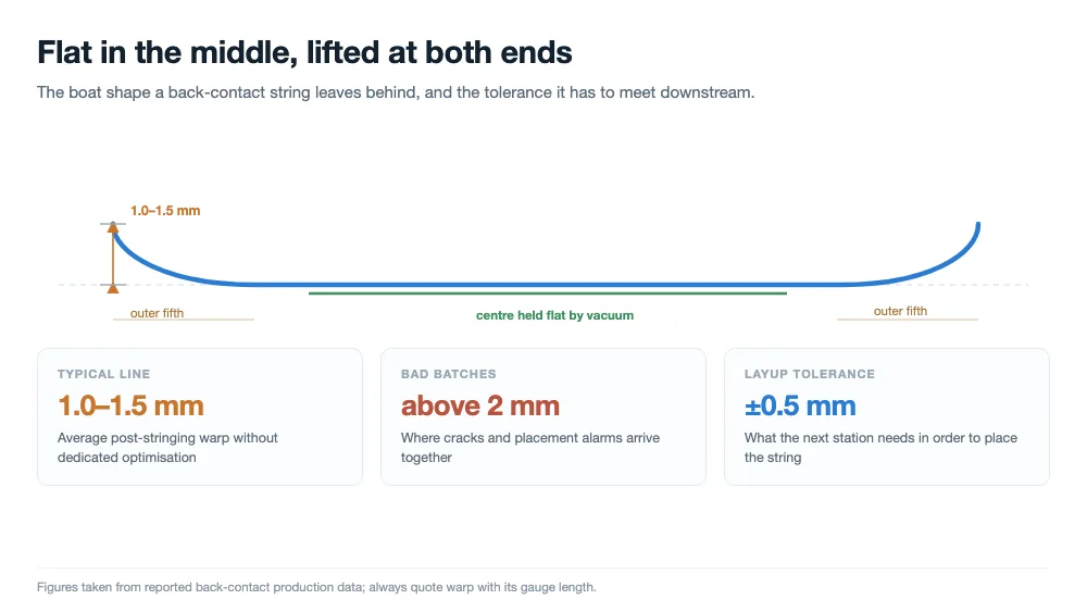
A stringer that welds back-contact cells badly does not usually fail loudly. The cells come out with the middle pressed flat to the platen and both ends standing a little proud, the way a sheet of paper lifts when you hold only its centre. The joint looks fine under the microscope. The defect shows up two stations later, when the layup robot cannot find the pad edge it expected.
Operators call it the boat. The shape is consistent enough to diagnose from a photograph: low in the middle, high at the ends, with most of the lift in roughly the outer fifth of the cell in the feed direction. This article is about that shape — what produces it, what it costs downstream, and the five settings that bring it back under control. If you want the material science behind why back-contact cells bow at all, that is covered separately; here we stay on the line.
The shape is the diagnosis
Warp after stringing has three measurable characteristics, and each one points at a different cause. Measure them before changing anything, because a number taken after a parameter change tells you nothing about where you started.
| What you see | What it usually means | What to record |
|---|---|---|
| Ends up, middle flat, symmetric | Thermal imbalance plus unconstrained ends — the classic stringing signature | Warp at the outer fifth of each end, both faces |
| One end higher than the other | Asymmetric tension or a platen that is not flat across the full width | Which end, and whether it moves with ribbon reel changes |
| Edge curl rather than end curl | Incoming wafer stress, not the weld | Warp of the same cells before they enter the machine |
| Warp that grows after a day | Residual stress still relaxing — measure again at 24 hours | Warp at 0, 1 and 24 hours on the same sample |
The numbers that matter are absolute, not relative. A line without dedicated optimisation typically reports 1.0–1.5 mm average warp after stringing, with bad batches crossing 2 mm. The layup station that receives those strings needs to place them within ±0.5 mm. Anything above that tolerance is not a cosmetic issue; it is a placement error waiting to happen, and the string does not have to be visibly bent to fail.
One practical note on measurement: quote warp as a height over a defined span, and say which span. A number without the gauge length cannot be compared between factories, and most disagreements about whether a batch is “in spec” are really disagreements about how it was measured.
Why the ends and not the middle
A front-contact cell is heated from the rear too, but the front carries a full metal grid. Heat spreads across both faces, the two sides expand closer to together, and the residual stress after cooling is small enough that a 150 µm wafer absorbs it. A back-contact cell has no front metal. All the heat enters the rear, the front stays cooler, and during cooling the rear contracts more than the front. The cell wants to curl, and it curls toward the front.
Where the curl becomes visible is decided by the fixture, not the metallurgy. A conventional platen holds the cell near its centre. The centre cannot move, so the strain is pushed outward and released at the ends, which are held by nothing. The result is not a uniform bow but a hinge at each end — exactly the boat shape operators report, and exactly the region where busbar or pad-edge placement is most fragile on a back-contact layout.
This is also why cooling rate matters as much as peak temperature. A fast drop locks the mismatch in before the cell has a chance to relax; a slower ramp lets the ribbon and the solder accommodate part of it. Two lines running the same peak on different cooling profiles will report different warp, and neither is lying.
Four multipliers that turn a small imbalance into a defect
The thermal asymmetry is the root cause, but on its own it produces a warp a layup station can live with. What turns it into 2 mm is a set of multipliers that stack.
Ribbon tension borrowed from a busbar line
Back-contact modules run fine ribbon in the 0.15–0.22 mm range, and thin ribbon amplifies whatever tension it is given. The ribbon expands while hot and contracts while cooling; if the tension is set high, that contraction pulls on the cell edge instead of straightening the strip. The end sections also carry the concentrated heat of the busbar joint, so they shrink more than the middle. Copying a front-contact tension recipe onto a back-contact product is the single most common human cause of excess end warp — the recipe looks conservative because it worked on the previous product.
A wafer half as stiff as the one the recipe was written for
Volume back-contact cells sit at 100–120 µm, against roughly 150 µm for the mainstream front-contact wafer. Stiffness falls faster than thickness, so the same bending moment produces noticeably more deflection. A recipe tuned on 150 µm silicon is not a slightly wrong recipe on 110 µm silicon; it is a different process.
Stress that arrived with the cell
Cells leave the cell line with residual internal stress from firing and metallisation. Soldering is a stress-release event: the cell is heated, the stress partially relaxes, and because the ends are free the release shows up as deformation. Industry estimates put incoming stress at more than 30% of the total warp contribution, which is why a line that fixes only the welder can plateau above target.
A platen that holds the centre only
Centre-only vacuum is the default because it is adequate for front-contact cells. On a thin back-contact cell it converts a symmetric strain into a visible hinge. This is a machine constraint rather than a recipe one, and it is the lever most often left untouched because it looks like capital expenditure rather than process work.
What the warp costs after it leaves the welder
End warp is not a single-station defect; it travels. The string reaches the busbar station with its ends lifted, and the busbar joint — already the least forgiving joint in the module — is welded across a gap that changed after the machine was set up. That is one path to the cold joints and lifted joints that show up later as lamination cracks.
At layup, the vision system looking for a pad edge or a fiducial finds the surface at a different height and, more importantly, at a different angle. Placement offset alarms follow, and the flip and transfer steps handle a bowed string with a suction cup that only touches part of it. Every one of those steps adds a breakage risk that is attributed to handling rather than to the stringer that caused it.
At lamination the stress is released rather than added — the module is pressed flat and held hot for minutes, and the residual stress either relaxes into the encapsulant or concentrates at a joint. If it concentrates, the result is a microcrack that never appears on the post-string EL image. That is why a line can pass its EL check and still ship a module with a cracked cell.
When laminating strings with residual warp up to 1.5 mm, we stage the chamber pressure and platen heat gradually so encapsulant flows around the joints before full mechanical load clamps the cells flat.
The long-term cost is fatigue. A joint under residual stress cycles through a wider strain range than a stress-free one, so it reaches failure earlier in thermal cycling. You pay for the warp twice: once in the yield of the day, and again in the field data four years later.
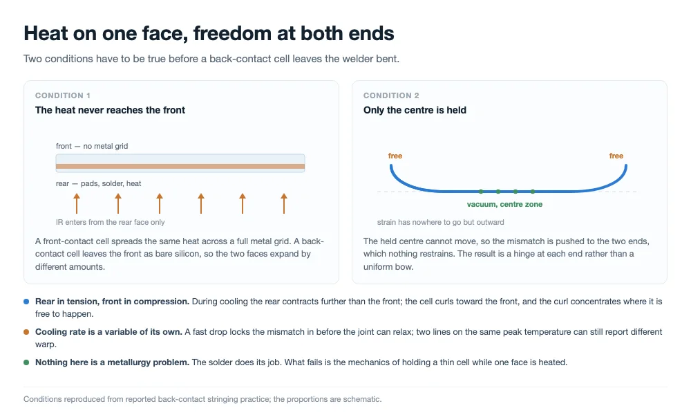
Rear-side heat, a cooler front, and two unheld ends: the strain has only one place to go.
Five levers, and the settings that matter on each
Warp control is a system problem, and adjusting one lever well while leaving four alone produces a modest improvement and a new defect. The five below are ordered by how much they change the result per week of engineering effort, not by cost.
| Lever | Setting that matters | What to verify |
|---|---|---|
| Thermal field | Front preheat 80–100 °C, front-to-rear difference under 50 °C, end-zone power 10–15% below centre | Measured front and rear temperature on the same cell, not the setpoint |
| Tension | Closed-loop constant tension, end sections 20–30% lower, 0.5–1 mm shrinkage allowance at the ends | Tension at the reel, at the end section, and after a reel change |
| Incoming material | Full warp inspection and binning, dedicated recipe per bin, pre-anneal at 100–120 °C for about 30 s | Warp before and after the pre-anneal on the same batch |
| Hold-down | Full-width porous platform with edge vacuum, hold 1–2 s after the joint until the cell is below 80 °C | Cell temperature at release, not the timer setting |
| Recipe discipline | Peak 5–10 °C lower with a longer hold, one library per wafer thickness and ribbon spec | That the recipe on the machine matches the product on the belt |
1. Reduce the front-to-rear gradient before anything else
The cheapest large improvement is a low-temperature preheat table in front of the weld zone, bringing the front face to 80–100 °C so the rear does not have to do all the work. Combined with segmented power — end zones 10–15% below the centre — the cell arrives at peak with a smaller gradient across its thickness. A three-stage profile of preheat, weld and hold replaces the abrupt ramp and drop that locks stress in. For the temperature dynamics of an infrared pulse on thin cells, the measured profile data is the useful reference.
2. Take the tension out of the ends
Closed-loop tension control does not remove ribbon shrinkage, but it keeps the tension constant from reel start to reel end, which is where most drift enters. Dropping the end sections by 20–30% relative to the middle lets the ribbon contract without pulling the cell edge, and leaving 0.5–1 mm of slack at each end gives the contraction somewhere to go. If the ribbon arrives with its own residual stress from drawing, a low-temperature anneal before it goes on the machine removes a variable you cannot otherwise control.
3. Sort the cells before they reach the welder
A warp gauge at the loader and two or three bins is enough. High-stress cells run a separate, gentler recipe instead of dragging the whole line down to their standard, and a pre-anneal station at 100–120 °C for about 30 s releases part of the incoming stress while the cell is still flat and unsupported. This is the lever that costs the least and is skipped most often, because it sits before the machine rather than in it.
4. Hold the whole cell, not the centre
A full-width porous platform with vacuum at the edges removes the hinge. The detail that decides whether it works is the release: holding for 1–2 s after the joint, until the cell is below 80 °C, lets the cell cool under constraint instead of springing as soon as the nozzle lifts. Most lines that install edge vacuum and see no change are releasing too early, and the fix costs a timer rather than a machine.
5. Slow the peak instead of chasing it
A peak 5–10 °C lower with a longer hold produces a joint of the same strength with less strain locked in — provided the solder actually flows. That condition is why recipe libraries matter: wafer thickness and ribbon spec both change the window, and a line running three products on one library is optimising for the average of three different processes. Keep one library per combination and make the machine select it, not the operator.
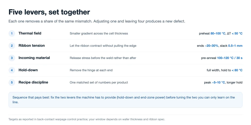
The five levers are not alternatives. Each one removes a share of the same mismatch.
What a change of this kind actually delivers
A back-contact mass-production line that applied the five levers together reported average post-stringing warp falling from 1.2 mm to under 0.5 mm, with warp-related rejects down by more than 85%. The downstream numbers moved with it: layup placement offset and lamination microcrack rate both fell, which is the part that matters commercially because those were being counted against the layup and lamination stations rather than the stringer.
Treat that as a reported result from one line, not a guarantee. What transfers is the method: measure warp at a stated span on the same sample before and after, hold everything else constant, and change levers in the order above. A line that changes five things at once and gets a better number learns nothing it can repeat next quarter.
The verification that convinces a customer is not a warp number on its own. It is a matching pair of images — EL after stringing and EL after lamination on the same string — plus the placement offset distribution across a full shift. Warp is a proxy; the two things you actually care about are a joint that stays intact and a pad edge the robot can still find after the module is pressed flat.
We compare electroluminescence images before and after the lamination stage on every test run, checking whether strings with up to 1.2 mm warp develop microcracks when pressed flat under heat.
Three traps that keep a line stuck
Lowering the temperature and nothing else. A cooler peak reduces one term in the mismatch and adds a risk of its own: the intermetallic layer may not form properly and the joint becomes a cold joint that passes a visual check. Temperature is the easiest lever to reach and the least effective on its own.
Reusing the front-contact recipe. A back-contact cell differs in the face that is welded, the wafer thickness and the ribbon cross-section. A recipe is a matched set of numbers for one combination of those three, and reusing it is not a shortcut but an untested process running in production.
Tuning the welder while ignoring incoming stress. With more than 30% of the contribution arriving before the cell reaches the machine, a line can spend weeks on the weld zone and never reach target. Sorting and pre-annealing at the loader is unglamorous and it is where the remaining margin usually is.
Frequently asked questions
Is end warp specific to back-contact cells?
The mechanism is not, but the severity is. Front-contact cells show the same thermal asymmetry and absorb it because the front metal spreads heat and the wafer is thicker. Back-contact cells combine single-sided heating, thin wafers and fine ribbon, which is why the same stringer produces acceptable warp on one product and a boat shape on the other.
What warp figure should a line aim for?
Below the layup station's placement tolerance, with margin. If the layup needs ±0.5 mm, a target of 0.5 mm leaves nothing for batch variation. Lines that report success land under 0.5 mm on average with the tail contained, which is why the reject rate matters as much as the mean.
Can a stringer be retrofitted with edge vacuum?
Usually yes, on machines whose platen is a replaceable module rather than part of the frame. Ask for the platen drawing and the vacuum zone map before assuming it is a bolt-on; on some platforms the change touches the vacuum distribution and the release sequence, not just the plate.
Does a lower peak temperature reduce throughput?
It reduces the heat input rate, so dwell usually has to rise to keep the joint sound. Whether that costs throughput depends on whether the machine was dwell-limited or index-limited. A stringer running well below its rated cycle is typically index-limited, and a longer dwell costs nothing; check which constraint you are on before trading cycle time.
Why does warp sometimes look worse a day later?
Residual stress keeps relaxing after the string cools. A measurement taken at the machine outlet captures the elastic part; the viscoelastic part develops over hours. Measure at 0, 1 and 24 hours on a sample if downstream complaints do not match the numbers you record at the stringer.
Do 0BB connections change the warp picture?
They change the timing. Adhesive and film-based interconnection move part of the connection to the laminator, so less heat enters the cell at the stringer and less strain is locked in early. The trade is that defects surface later, after lamination, when the module is worth more. The hold-down and cooling logic still applies; the measurement point moves.
Is warp a reason to reject a cell supplier?
Only with data. Incoming warp varies by batch, and a supplier that looks bad on one lot may look average across ten. Binning and a dedicated recipe usually recover the yield without changing suppliers; a specification change is the right move when the distribution itself shifts and stays shifted.
Which of the five levers should a new line specify first?
Full-width hold-down and segmented end-zone power, because those are decided when the machine is specified and are expensive to add later. Preheat and tension control are usually available as options; incoming binning and pre-anneal are process decisions you can make on day one without buying anything.
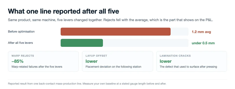
One reported line, five levers together. The method transfers; the number is a starting point, not a promise.
Final thoughts
End warp is the visible signature of a single-sided process running on a thin cell that is held in the wrong place. Fixing it is not a matter of finding one correct temperature; it is five settings that each remove a share of the same mismatch, and the ones that pay best are usually the ones outside the weld zone — a sorted, pre-annealed cell and a platen that holds the whole width until the joint is cool.
If you are specifying a platform for back-contact production, the question to ask is not what peak temperature it reaches but how it holds and releases a 110 µm cell. That answer decides the yield you will report in month six.
Related reading:
- Why BC Solar Cells Are More Prone to Bowing and Warpage
- PV Ribbon Structure and Types: Flat, Round and Shaped
- 0BB on Back-Contact Solar Cells: Gains and Yield Limits
- BC Cell Compatibility: Six Makers, One Tabber Stringer
- Tabber and Stringer Machine: How It Works, How to Choose
- Why Bussing Overlap Soldering Causes Cell Cracks During Lamination
- PV Ribbon Soldering: The Joint, the Window, the 0BB Shift
- SS-2500B Full Automatic Solar Cell Tabber Stringer
For back-contact modules sensitive to cell curl and joint stress, OOITech builds single and double chamber solar panel laminator machines with oil-heated or electric platens to control thermal uniformity. Send us your drawings, a module stack, or string samples for process evaluation, and we will verify the recipe parameters on our test equipment.