Editorial responsibility for this article rests with Wuhan Ooi Photoelectric Technology Co., Ltd. Written and reviewed by the Ooitech editorial team. See our editorial policy for how we write, where AI tools are used, and how to request a correction.
MC4 Contact Resistance: The Field Crimp Is the Weak Link
Table of Contents
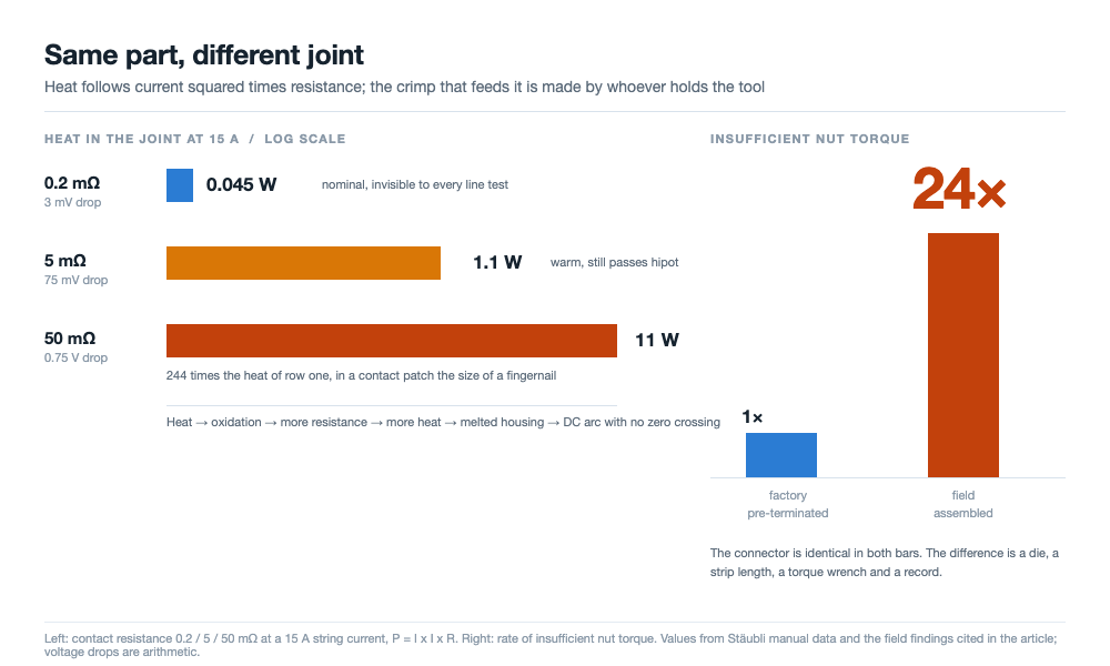
Quick answer: A connector fails in one place: the interface where two metal surfaces meet, and the heat it makes follows I²R. At 15 A a joint at 0.2 mΩ dissipates about 0.045 W, which is nothing. At 5 mΩ it is about 1.1 W. At 50 mΩ it is 11 W inside an area the size of a fingernail, and the loop from there to a melted housing and a DC arc has no brake in it. Nothing else in a bill of materials depends as much on who did the work. Factory pre-terminated connectors arrive with a crimp made on a calibrated press, a checked die and a sampled pull test. Field-assembled connectors show insufficient nut torque about 24 times as often, and a 2019 investigation of Dutch rooftop fires attributed more than 80 percent of its cases to connector installation faults or cross-mating. The variable you can act on is not brand or rating. It is where the crimp was made, and whether the torque was recorded.
Two connectors with the same part number can leave two factories with a tenfold difference in joint quality. The plastic is identical. The difference is a crimp, a die, and a torque value nobody wrote down.
The arithmetic: 11 W in a fingernail
Contact resistance is the only root cause worth tracking, because every other failure mode either raises it or is raised by it. Water ingress corrodes the contact, a relaxed spring lowers pressure, a loose barrel narrows the path. All three arrive as one number, and that number turns into heat.
At a string current of 15 A, one mated pair behaves like this:
| Contact resistance | Drop at 15 A | Heat in the joint | In service |
|---|---|---|---|
| 0.2 mΩ | 3 mV | 0.045 W | Nominal for a fresh pair, invisible to every line test |
| 5 mΩ | 75 mV | 1.1 W | Warm to the touch, passes an insulation test anyway |
| 50 mΩ | 0.75 V | 11 W | Fingernail-sized heater, housing softens, arc risk climbs |
Eleven watts does not sound like much until you divide it by the area. A mated pair presents a contact patch of a few hundred square millimeters, so the power density softens a PA housing well below its 115 °C limit.
Then the loop closes on itself. Heat accelerates oxidation of the plating, oxidation raises resistance, resistance raises heat, and the spring holding contact pressure relaxes as the metal yields. The end is a melted housing and a DC arc, which has no zero crossing to go out at, so a warm joint finishes as a fire.
Every figure there is a property of the joint, not the product.
Parallel louvers buy time, not immunity
The contact system in an MC4 is a MULTILAM band: a ring of stamped copper-alloy blades, louvered so each blade is an independent spring, set into the socket wall. Each blade meets the 4 mm pin at its own point, and all of those points are in parallel.
That geometry delivers three things, and they decay on different schedules. The parallel points divide the current, so contact resistance is low, nominally under 0.2 mΩ for an MC4-Evo 2. The blades stay elastic through thermal cycling, so contact pressure does not follow the housing. And one degraded point does not open the circuit, so the joint declines gradually rather than in a step.
Gradual is not safe, and this is where the reputation of the format gets over-read. The louver band protects the pin-to-socket interface. It does not protect the barrel where the cable strands are crimped. That joint is in series, it has no redundancy, and the connector maker does not make it. Whoever strips the cable, inserts the bundle and closes the die makes it, and on a rooftop that is a technician with a hand tool.
Four defenses, and one of them leaves the factory undone
The part is built around four barriers, and it helps to know who performs each one, because that decides whether a defect is caught.
| Defense | What it protects | Who performs it | Checked later |
|---|---|---|---|
| Contact band | Resistance at the pin | Connector maker | Only by measurement |
| Sealing: interface O-ring, gland at the cable tail, closed by the locking nut | The corrosion path | Maker at the interface, installer at the gland | Visually, not the compression |
| Latch: tool required to unlock | Separation under wind and cable load | Maker | Yes, visibly latched |
| Material and termination: tin-plated copper, PA UL94-V0, salt mist tested, cold crimp | Environment and joint quality | Maker for material, installer for the crimp | Crimp height, sample only |
The sealing claim is IP65 or IP68, with a manual value of 1 m for 168 hours. The latch exists for a regulatory reason as much as a mechanical one: from 2008 the US National Electrical Code required PV connectors to need a tool to open, and a self-locking latch met it in one part, which is much of why this format survived. Rated voltage is 1500 V DC under IEC and UL, and the next step up changes the qualification the part needs, not the physics at the contact: the move to 2000 V lands on this same component.
Read the last column again. Three barriers are properties of the part as shipped. The fourth, termination, is a process performed by a person, and it is the only one whose quality leaves no trace.
What the same-maker rule demands of a line
IEC 62852 covers the connectors, IEC 62548 covers array design, IEC 60364-7-712 covers PV installations. All three require that two halves which mate come from the same manufacturer and the same type, and IEC 61730-1 now requires the connector type on the module nameplate. For a module factory those clauses land in three places.
- The bill of materials stops being local. If the inverter, combiner box or optimizer ships with a specific connector type, your lead has to match it or the installer builds a mixed pair on site. What mixing does to ratings is in the MC4 versus MC4-Evo 2 comparison; what matters here is that the pairing is settled in purchasing, months before anyone sees a roof.
- The nameplate mark makes the connector a declared characteristic. A substitution stops being a purchasing convenience and becomes a change to a certified document, which is audited.
- Second-sourcing for price moves the interface to the installer. Your lead meets a device you did not choose, and the person joining them cannot know the halves were never qualified as a pair.
None of that argues for one brand for its own sake. It argues for treating the connector as a system boundary, which is what a nameplate entry makes it.
The crimp is made in the wrong place
Here is the number that should reorganize how you think about the part. A field-assembled connector shows insufficient nut torque about 24 times as often as a factory pre-terminated one. Not 24 percent more often. Twenty-four times.
Left: one physical quantity, heat at 15 A, rising from 0.045 W at 0.2 mΩ to 11 W at 50 mΩ. Right: one process ratio, field-assembled connectors reaching insufficient nut torque about 24 times as often as factory pre-terminated ones.
That is roughly one order of magnitude, and it separates a process from an improvisation. A factory crimp is made on a press with a die matched to the connector and cable, at a set strip length, with crimp height checked against a drawing. A field crimp uses whatever tool is in the van, one-handed at height in gloves, and almost never with a record.
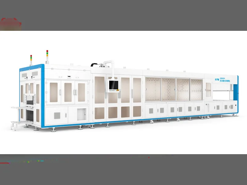
We standardize this step on our assembly line by matching calibrated dies to cable cross-sections, verifying crimp dimensions against drawings so initial contact resistance stays at the nominal 0.2 mΩ level under 15 A.
Under-torque damages two things at once. The locking nut compresses the gland seal at the cable tail, and it clamps the cable. Too little torque leaves the seal uncompressed, which opens a moisture path toward the barrel, and leaves the conductor unheld, so strand cold flow loosens the joint and resistance climbs. One error, two failure modes, neither visible from outside.
Torque is the item nobody records
A torque value is the cheapest evidence in a PV plant and the most often missing. With a wrench set to a value and signed off, the argument after a fault is about the value. Made by feel, it is about memory. The 24 times figure is what happens when a calibrated step becomes an uncalibrated one.
Every mate cycle costs resistance
Mating is not free. Reported figures put the resistance increase at about 10 percent after 10 cycles and about 30 percent after 50, because each cycle abrades the plating and the debris stays in the band. Commissioning becomes a wear process: every re-plug for a test leaves resistance higher.
Two habits follow, both free. Never mate or unmate under load, because a DC arc at 15 A erodes the contact in a way no cleaning recovers. Put a dust cap on any connector that will sit unmated, because open exposure damages the contact and the sealing face, the two surfaces the IP rating rests on.
| Dimension | Factory pre-terminated | Field-assembled | Evidence held by |
|---|---|---|---|
| Crimp tool | Calibrated press, matched die | Hand tool, often unspecified | Line |
| Torque | Set by machine | A wrench if one is in the kit, rarely recorded | Installer |
| Check after closure | Pull test per sample, crimp height per drawing | None | Quality |
| Under-torque rate | Reference level | About 24 times the reference | Not assigned |
What 24 times looks like once it is on a roof
Two European surveys point the same way from opposite ends. In the Netherlands, a TNO investigation of rooftop PV fires published in 2019 attributed more than 80 percent of the cases studied to connector installation faults or cross-mated connectors. In the UK, a 2017 BRE survey likewise listed DC connectors among the main points of fire origin. Both reach us through a PV Tech review, not the originals, which affects precision and not direction.
Reading those percentages honestly
A fire investigation is a biased sample: it holds the failures severe enough to investigate and none of the near-misses a plant walks past. So 80 percent is not the probability that a connector starts a fire. It is what was found when fires were traced to a cause, and it says connectors dominate that list.
Connector work is high-consequence and low-visibility. Nothing on a construction schedule rewards a torqued gland, and nothing fails when the step is done. The failure surfaces years later, in a junction that was already marginal when the scaffolding came down.
The last electrical interface before the module is boxed
A module leaves the line with two leads and two connectors, and those are the last electrical interfaces the factory touches. Everything upstream sits inside a process with measurements attached. The connector is where the product becomes an installation.
That is the argument for treating termination as a line process. Four controls carry most of the weight.
- Pre-terminate on the floor that made the module. The lead is cut, stripped and crimped in the same building, with the die and the pull test under your control. The junction box soldering machine closes the box onto the lead and potting the box seals the interior, but nothing in the box protects the crimp outside it.
- Treat die and cable as one specification. Connector, cable and die are three parts of one crimp. Change the cable supplier and the die number may change, and a pull test on the old combination proves nothing about the new one.
- Record torque for anything done by hand. If a step cannot be done by machine it needs a tool with a setting and a signature, which is the only thing that makes the 24 times figure auditable.
- Check the joint, not just the insulation. A hipot and a continuity test pass a loose barrel at low current, because neither measures joint resistance. A four-wire reading does.
Three of those four are procedures rather than purchases, and the fourth uses an instrument most lines already own. The risk sits in a step, not in a specification.
Pre-terminated or field-terminated: the actual trade
Field termination survives on logistics. Bulk cable ships on a drum and is cut to length on site, so nothing is wasted on a 40 m home run. Pre-terminated leads ship at a fixed length with the connector already crimped, and a wrong length is scrap. On a rooftop job full of short irregular runs, that difference is real money.
The trade is a logistics saving against the removal of a process from the critical path. Field termination takes a step with a 24 times higher under-torque rate and hands it to whoever has the least supervision, calibration and record-keeping.
What a pull test proves, and what it does not
A pull test proves that a specific die, on a specific cable, at a specific strip length, produced a joint above a threshold on the samples taken. It does not prove the seal or the nut torque, and it says nothing about units that were not sampled. Sampling validates a process, never a unit.
We pair destructive pull tests on sample batches with four-wire electrical checks, confirming that crimped terminations maintain mechanical hold while keeping contact resistance near the 0.2 mΩ level before cables are routed into junction boxes.
The question of ownership follows. A connector that fails two years later is an argument between a module maker, a cable supplier, an installer and a brand. If the crimp was made in your factory there is one party to it, which is usually worth more than the freight difference.
Where these numbers come from
The product values and field findings here come from a Chinese-language technical article on the MC4 connector, which cites Stäubli manuals and a PV Tech review of connector failures. Every figure above comes from it: the three resistance cases with their watt results at 15 A, the nominal 0.2 mΩ, the IP65/IP68 rating at 1 m for 168 hours, UL94-V0, the 115 °C limit, the 24 times ratio, the 10 and 30 percent increases over 10 and 50 cycles, the TNO and BRE findings and the 2008 NEC clause.
Three things are ours. The voltage drop column is arithmetic: 15 A through 0.2, 5 and 50 mΩ gives 3 mV, 75 mV and 0.75 V, The claim that the louver band does not protect the barrel crimp, and the assignment of each defense to a party in the second table, are our reading rather than the source.
Two items are common electrical practice rather than findings: a DC arc has no zero crossing and does not self-extinguish, and strand cold flow loosens a joint that was never fully clamped. The TNO and BRE percentages reach us through the PV Tech review and we have not read either original, so trace them before they go into a specification. The type-test pattern is the one in the module reliability test list: a type test proves a design, not an installation.
Frequently asked questions
Q: Does contact resistance matter more than the current rating?
At a fresh joint, no. The rating is what the part is certified to carry, and a new pair ignores resistance. The difference is that only the resistance changes on site.
Q: Why is a field crimp worse when the connector is the same?
Because the connector is one of three inputs, alongside the die and the operator. A factory fixes both and samples pull strength; a field kit leaves them to whoever holds the tool.
Q: How much resistance does re-plugging add?
About 10 percent after 10 cycles and about 30 percent after 50, on the figures reported in the source. That is small against 0.2 mΩ and large against the margin you were relying on.
Q: Can a four-wire measurement catch a bad crimp?
It catches the resistance a bad crimp produces. A two-wire meter reads its own lead resistance too, so at these values the reading is dominated by the wrong thing. A four-wire check against a known-good joint fixes that.
Q: Is the 24 times figure only about torque?
It is stated for insufficient nut torque, and torque is the cleanest indicator because it is measurable and almost never measured. Strip length, strand insertion and die choice show the same gap, unrecorded.
Q: Do the TNO and BRE surveys prove that connectors cause fires?
They show that when rooftop fires were investigated and traced, connectors were the dominant factor, with more than 80 percent of the Dutch cases linked to installation faults or cross-mating. That is not a failure rate.
Q: Should a module line pre-terminate its leads?
It should decide deliberately. Pre-termination keeps a measurable process inside your factory; field termination saves logistics on short irregular runs. The choice should follow who holds the evidence when a joint fails.
Q: What does the same-maker rule require of a factory?
That it is chosen with the downstream device in mind, declared on the nameplate under IEC 61730-1, and not substituted without a documentation change. Three standards require mating halves from one maker and type.
Final thoughts
The connector is not a commodity and not a spec sheet either. It is a joint somebody makes. Every barrier in the design, the louvered band, the O-rings, the latch, the flame-retardant housing, protects a contact that stays at 0.2 mΩ only if the crimp was closed properly. Twenty-four times is not a small process gap. It is the difference between a product you can certify and an installation you can only hope for.
We supply the CHT9980A and CHT9981A PV safety comprehensive testers to verify hipot, insulation resistance, and ground continuity on finished solar modules and lead assemblies. Send us your module stack, cable drawings, or connector samples for evaluation to determine appropriate test parameters for your production line.