Editorial responsibility for this article rests with Wuhan Ooi Photoelectric Technology Co., Ltd. Written and reviewed by the Ooitech editorial team. See our editorial policy for how we write, where AI tools are used, and how to request a correction.
Creepage in a Junction Box: Why 1500 V Changed the Design
Table of Contents
Quick answer: Creepage distance is the shortest path along an insulator surface between two conductors. Clearance is the shortest path through air. They fail for different reasons, so a drawing that satisfies one can fail the other, and on a 1500 V module the surface path is the one that causes trouble. Inside a junction box the number is not lifted from a datasheet: it is read from working voltage, pollution degree and the tracking index of the material, then doubled for reinforced insulation. At the 1600 V tier, a box in group I material at pollution degree 2 needs 8 mm for basic insulation and 16 mm for reinforced. Move to group III at pollution degree 3 and the same requirement becomes 25 mm and 50 mm. A palm-sized box cannot find 50 mm, which is why potting and material choice are structural decisions, not finishing steps.
Every junction box ships with a type-test report, and that report contains a measurement sheet with two columns that look interchangeable. They are not, and reading them as one is how a 1000 V design gets a new label.
Two numbers that protect against different failures
Clearance is the air gap. It exists to stop a flashover: a lightning surge, a switching transient or a system fault puts a fast, high voltage across the gap, the air ionizes, and an arc bridges it. Clearance therefore depends on impulse withstand voltage and on altitude, since thinner air breaks down earlier. It does not depend on what the plastic is made of.
Creepage is the surface route. It exists to stop tracking: dust, salt and condensed moisture form a weak conductive film on the surface, small discharges run along it, the polymer carbonizes in a narrow line, and that line becomes a conductive path that does not go away. The driver here is the long-term working voltage and how dirty the surface gets, plus the material resistance to tracking.
The practical consequence is a rule that is easy to state and easy to forget: for the same pair of conductors, creepage is never smaller than clearance. The surface route goes around whatever the air gap crosses. If your drawing shows creepage below clearance, you are measuring one of them wrongly, most often by taking a shortcut across a groove that the standard says must be bridged.
Three variables, one table
IEC 62790 covers junction boxes for photovoltaic modules up to 1500 V DC designed as class II, that is, with double or reinforced insulation. The numbers themselves come from the insulation coordination base standard, IEC 60664-1, and they are read from a table using three inputs.
- Working voltage. The long-term voltage between the two conductors, taken as the DC value. Higher voltage sustains a surface discharge more easily, so the required distance grows. Going from a 1000 V system to 1500 V is a step to a new row in that table, not a small increment within a row.
- Pollution degree. The micro-environment of the surface. Degree 1 means no pollution or only dry, non-conductive pollution. Degree 2 means normally non-conductive pollution with occasional temporary conductivity from condensation. Degree 3 means conductive pollution, or dry pollution that becomes conductive when it condenses. An exposed outdoor surface is degree 3; a well-sealed interior is often assessed as degree 2.
- Material group. The comparative tracking index, the voltage a surface withstands under repeated drops of electrolyte before a tracking path forms. Group I is 600 and above, group II is 400 to 600, group IIIa is 175 to 400, group IIIb is 100 to 175. A higher index buys a shorter distance.
Then comes the insulation type. A live part to a touchable surface is reinforced insulation, and its required creepage is generally twice the basic value. Put the three variables and the insulation type together and you get the table below, for the 1600 V tier that a 1500 V system usually lands in.
| Condition | Group I, CTI ≥ 600 | Group II, CTI 400–600 | Group III, CTI below 400 | What it means for a box |
|---|---|---|---|---|
| Pollution degree 2, basic insulation | 8.0 mm | 11 mm | 16 mm | The comfortable case: a sealed interior, a good material, a layout that fits |
| Pollution degree 2, reinforced insulation | 16 mm | 22 mm | 32 mm | Still layout work, but achievable with ribs and a partition |
| Pollution degree 3, basic insulation | 20 mm | 22 mm | 25 mm | Exposed outdoor surface, or an interior that is not kept dry |
| Pollution degree 3, reinforced insulation | 40 mm | 44 mm | 50 mm | The corner that ends the discussion: not buildable in a palm-sized box |
Values as tabulated in the source article for the 1600 V tier of IEC 60664-1, with reinforced insulation at twice the basic value and group III read as IIIa. Treat them as the shape of the requirement, not as a substitute for the current edition of the standard.
Read the bottom-right corner first. A box with low tracking index, with live parts exposed to a degree 3 environment, and required to hold reinforced insulation, needs 50 mm of surface path. There is no arrangement of ribs inside a junction box that manufactures 50 mm honestly. That single cell explains most of the design decisions in the product category.
The same requirement, drawn six ways
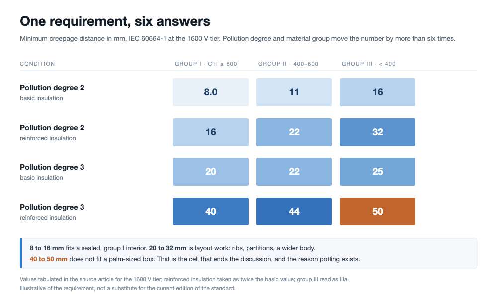
One requirement, six answers. The same 1600 V working voltage needs 8 mm in the top-left cell and 50 mm in the bottom-right, before any tolerance for measurement.
The point of the matrix is not the numbers but their range. Between the top-left cell and the bottom-right cell the requirement grows by more than six times, at identical working voltage. Nothing about the module changed. What changed is where the surface sits and what it is made of, and both of those are choices made on a drawing and in a material specification sheet.
Where the paths actually run in a box
A junction box is small, so intuition says the distances are short and the problem is trivial. In practice there are three classes of path, with three different requirements, and only one of them is usually the hard one.
- Live part to outer surface. From a terminal or busbar, across the interior, through or around the body, to the outside of the housing and the backsheet mounting face. This is insulation to earth and is assessed as reinforced. It is the path that most often blocks a design, because it has to leave the box.
- Terminal to terminal. Adjacent terminals sit on either side of one bypass diode, which protects one substring, so the potential difference is tens of volts at most. This is functional insulation and its requirement is far lower. It is rarely the constraint, even though it is the path people measure first because it is easiest to see.
- Cable exit, seal and lid joint. Not usually the shortest path, but these are the routes by which moisture and contamination enter. They decide which pollution degree the interior can be assessed at, so they set the requirement for everything else. A perfect 16 mm interior inside a box that breathes is a 40 mm requirement in disguise.
Measurement has its own convention, and it is where drawings go wrong quietly. When the path crosses a groove, not every groove counts. If the groove is narrower than the specified width X, contamination bridges it, and the path is taken straight across the mouth of the groove. Only a groove wider than X contributes its walls and floor to the measured path. X follows the pollution degree: about 1.0 mm at degree 2 and about 1.5 mm at degree 3. Ribs and slots inside boxes exist precisely to lengthen the surface route within a fixed volume, and a rib narrower than X has been doing nothing at all.
Potting is a pollution-degree decision
Go back to the matrix and notice which variables you actually own. Working voltage is set by the system. The outer dimensions are set by the module, the backsheet space and the bill of materials. That leaves two levers: the material and the pollution degree. Production boxes pull both at once.
The material lever means choosing a high tracking index compound, typically a modified PPO or a PC grade. The catch is that the index is a property of the formulation, not of the polymer family: flame retardants, fillers and even colorants move it, and the same grade in a different color or from a different batch can land in a different group. A material qualification that copies the datasheet value and skips the tracking test has not qualified anything.
The pollution lever is where potting enters the argument. A potting compound that fully covers the live parts removes the surface from contact with air and moisture, which allows the pollution degree of that region to be assessed far lower. In the limit the requirement is no longer a surface path at all but solid insulation through the compound. IEC 62790 requires that any reduction of pollution degree by coating or potting satisfies the conditions of its Annex B, and the principle behind it comes from IEC 60664-3; the 2020 edition also added distances through cemented joints to its table 3.
That reframes what the glue line is for. Potting is usually described as moisture protection and thermal conduction. In the insulation argument it is also the thing that rewrites the pollution degree, and it only rewrites it while the compound is intact and bonded. A void, a shrink cavity or a debonded patch along a terminal does not reduce the insulation performance by a percentage. It locally reinstates the surface path you thought you had removed, at the full degree 3 requirement, in a place nobody measures.
What potting has to survive to keep that credit
Because the credit is conditional, the acceptance criteria for potting are electrical rather than cosmetic, and they need to be written that way on the process sheet.
On our line, we evaluate potted junction boxes by running dielectric withstand and insulation resistance tests up to 1500 V, confirming that no internal voids or curing defects compromise the required electrical isolation.
- Coverage and fill height. Every live part that the insulation argument depends on has to be under compound, at the specified height, on every unit. Weight or volume per shot is the cheap proxy; a cross-section on a first-off is the honest check.
- Voids and shrink cavities. Mixing ratio, degassing and cure profile decide these. A two-component meter-mix dispenser that holds ratio within a stated tolerance is what makes the argument repeatable, which is why the metering accuracy of the filling station is an insulation parameter and not only a cost one.
- Adhesion to body and terminal. The compound has to stay attached through damp heat and thermal cycling. Once it lifts, the surface is back, and the design margin goes with it.
- Evidence after aging. The credit is claimed after the aging sequence, not before. If the qualification report shows potting adhesion before damp heat only, the number in the table is not yet yours.
Why a 1000 V box does not become a 1500 V box
The most expensive version of this mistake is a commercial one: take a qualified 1000 V housing, print a new label, ship it into a 1500 V system. The voltage step moves the requirement to a new row in the table, and the existing geometry, the existing material group and the existing potting layout were all optimized for the old row. Sometimes the design still passes; the only way to know is to redo the surface measurement at the new voltage and re-run the relevant tests. The same logic applies one tier up: the move toward 2000 V systems does not only change cell and module design, it reopens the insulation coordination file for every component on the DC side.
It also matters which qualification you are standing on. IEC 61215 and IEC 61730 prove different things, and neither replaces the construction requirements of the other. Insulation coordination sits on the 61730 side, in the construction review, and the measurement sheet is evidence for that review rather than for performance. If the standard hierarchy itself is unclear in your organization, the relationship between IEC, UL, GB/T and group standards is worth settling before the next product change.
To satisfy IEC 61730 inspection points, we verify finished modules using safety testing sequences that combine hipot, insulation resistance, and wet leakage measurements on each production run before final packing.
What we would check before the next build
Five checks, in the order that finds problems cheapest.
- Read the requirement off the drawing, not the report. Take the actual worst-case path from live part to touchable surface, apply the groove rule with the right X, and compare with the table cell that matches your declared pollution degree and material group. Most failures are found here, on paper, for free.
- Verify the tracking index per batch and per color. Request the tracking test on the actual compound supplied, not a family datasheet. Record the group in the incoming inspection plan, and treat a color change as a new material.
- Inspect potting coverage on a section. One first-off per shift, cut and photographed, with fill height and void criteria written down. Cosmetic inspection of the outside of a box tells you nothing about the inside.
- Test insulation electrically, every unit. A dielectric withstand and insulation resistance test at the end of the line is the only check that sees the assembled article. Equipment such as the CHT9980A safety tester exists for exactly this gate, and the test limits should come from the construction requirement, not from a habit inherited from an older product.
- Keep the joint evidence with the product. The potting and the terminal weld are made on the same line, and a soldering step with a recorded profile is what lets you argue later that the surface under the compound was clean when it was covered. Contamination under potting is invisible and permanent.
Where these numbers come from
The six values in the matrix, the material group boundaries and the groove widths X come from the source article, which tabulates them for the 1600 V tier of IEC 60664-1 and notes that reinforced insulation is taken as twice the basic value and group III as IIIa. The standard numbers and their scope (IEC 62790 for junction boxes, IEC 60664-1 for insulation coordination, IEC 60664-3 for coating and potting, IEC 61730-1 for module construction) are as cited there.
What is ours: the reading of the matrix as a design-space argument, the order of the five checks, and the claim that potting is a pollution-degree decision before it is a waterproofing one. That claim follows from Annex B and IEC 60664-3, but the wording is our interpretation and your certification body has the final say. We have not measured the boxes in the photographs, and no number here comes from a test we ran.
FAQ
Q: Is creepage always larger than clearance?
For the same pair of conductors, yes. The surface route has to travel around whatever the air path crosses, so it cannot be shorter. A drawing that shows otherwise has a measurement error, usually a groove counted that should have been bridged.
Q: Which pollution degree applies inside a potted box?
That is the point of potting: the covered region can be assessed at a lower degree, or as solid insulation, provided the conditions of IEC 62790 Annex B are met. The uncovered region, and any void inside the compound, stays at the degree its environment implies.
Q: Does a higher tracking index always let me shrink the box?
It moves you a column in the table, which can cut the requirement by half. Whether that becomes a smaller box depends on the rest of the layout, and on whether the material still meets the mechanical and flammability requirements at that index.
Q: Can I use the supplier report for my own module qualification?
Only if the report covers the exact article, the exact material group and the exact pollution degree you declare. A report for a 1000 V box in a different color is evidence about a different product.
Q: What does the 1.0 mm and 1.5 mm groove rule change in practice?
It decides whether a rib counts. A rib narrower than X is bridged by contamination and contributes nothing to the measured path, so a layout full of thin ribs can measure far shorter than the drawing suggests. At degree 3 the threshold is the wider of the two, which makes thin ribs less useful still.
Q: Why is potting quality an electrical issue?
Because the insulation credit depends on the compound being continuous and bonded. A void or a debond reinstates a surface path at the full requirement of its environment, in a location that no routine inspection looks at.
Q: Does 1500 V change anything for the terminals?
Terminal to terminal is functional insulation and usually stays easy. The step matters for live part to outer surface, and for the creepage across the body and around the cable exit, which is where the reinforced requirement lands.
Q: Where does the module safety standard fit?
IEC 61730-1 sets the construction requirements, including insulation coordination, and IEC 62790 gives the junction box its own safety requirements and tests. The measurement sheet is evidence for the construction review; performance testing under IEC 61215 answers a different question.
Final thoughts
Creepage looks like a number to be measured and is really a decision to be made. Working voltage comes from the system and dimensions come from the module, so the two levers left are the material and the pollution degree, and both are settled long before the measurement sheet is filled in. Ask what pollution degree and what material group a box rating was qualified under, and whether the potting that supports it survived damp heat intact. That question costs nothing and finds most of the problems while they are still on paper.
OOITech supplies the CHT9980A and CHT9981A PV safety testers to perform hipot, insulation resistance, ground continuity, and wet leakage testing on production lines. Send your junction box drawings, module stack specifications, or test samples to our engineering team for evaluation and test parameter configuration.