How to Choose the Right Solar Module Laminator
Table of Contents
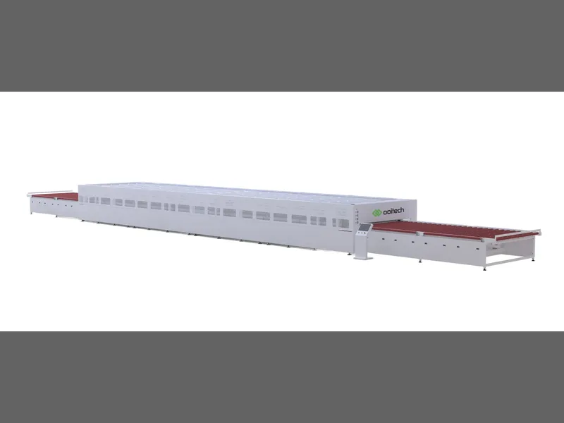
Quick answer: Choosing a solar module laminator starts from the module drawing and the lamination recipe, not from the annual MW figure on the brochure. Chamber size is the first decision because it fixes how many modules load at once: a 2200 mm by 3600 mm chamber was specified for three conventional 72-cell modules, a 2300 mm by 4600 mm chamber for four, and larger chambers for five, all based on older module formats that should not be reused for current large-format modules without a new layout drawing. A specification requiring at least 50 mm between modules means dividing platen area by module area overstates the load. A supplier that quotes capacity using 156 mm cells and 275 W modules will show a higher MW figure for the same machine. Compare saleable modules per hour instead.
PV Module Manufacturing · by Jerry, Ooitech
Product Overview & Selection Methodology
Selecting Based on Module Requirements
Selecting a solar module laminator requires looking beyond isolated equipment brochures. A laminator chamber size must match module dimensions, its cycle must match overall production line speed, and its vacuum and temperature profile must fit the specific encapsulant (EVA or POE). Equipment choice should originate from module drawings and lamination recipes rather than annual MW figures printed in promotional materials.
Advertised MW ratings often calculate capacity based on outdated module formats (e.g., 156 mm cells, 275 W modules). A higher module wattage inflates advertised MW even when total panel throughput remains identical. For objective evaluation, compare machines by saleable modules per hour:
Saleable modules per hour = modules per load × completed loads per hour × first-pass yield × uptime
Importance of Loading Drawings
Selection begins with module dimensions, glass thickness, layup details, encapsulant specs, and junction-box positions. A scaled loading drawing must demonstrate exact clearances. For instance, maintaining a 50 mm clearance between modules means simply dividing platen area by module area overstates load capacity. Chamber formats must be evaluated against modern large-format module dimensions.
Technical Parameters & Configuration Matrix
Chamber Architecture Selection
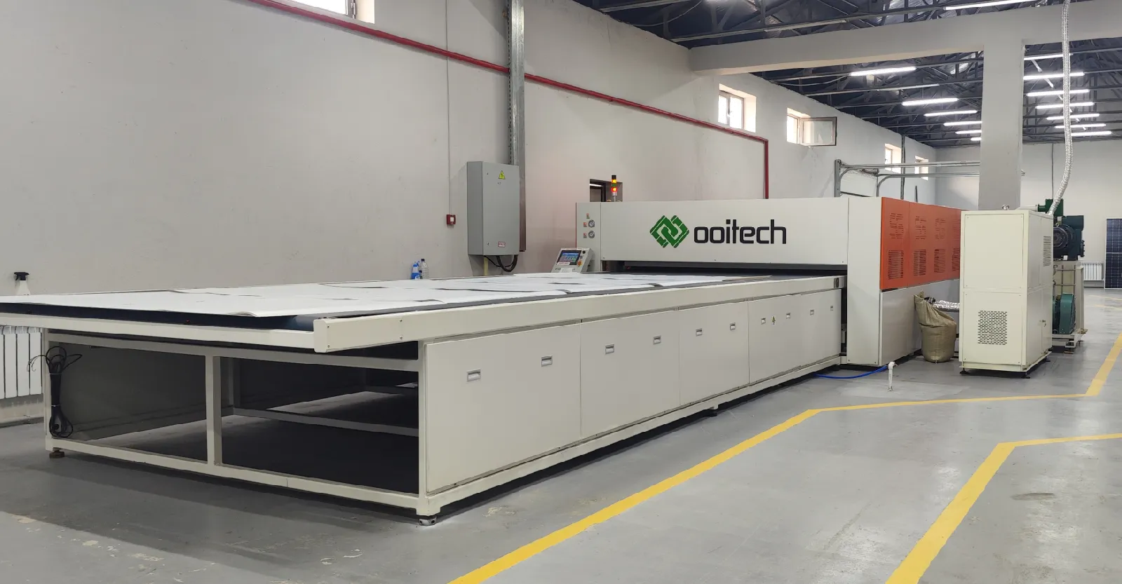
A single-chamber laminator performs evacuation, pressing, curing, and venting within one chamber. It features a smaller footprint and lower utility demands. Dual-chamber laminators separate lamination from curing, allowing one load to cure while the next load evacuates, doubling output per hour.
| Configuration | Effective Working Area | Quoted Work Cycle | Average Operating Power | Overall Size | Suitable Use |
|---|---|---|---|---|---|
| Semi-automatic | 1100 × 2200 mm | ≤18 min | ≤18 kW | 2.65 × 2.30 × 1.35 m | Repairs, pilot work, small modules |
| Automatic single chamber | 2200 × 3600 mm | ≤18 min | ≤30 kW | 12.1 × 3.15 × 1.8 m | Lower production volume |
| Automatic dual chamber | 2200 × 3600 mm per chamber | ≤9 min | ≤60 kW | 16.9 × 3.15 × 1.8 m | Continuous module production |
| Stacked dual chamber | Four 2400 × 4600 mm working levels | ≤9 min | ≤130 kW | 22.1 × 3.50 × 2.65 m | High output with limited floor area |
| Large dual chamber | 2700 × 8700 mm per chamber | ≤9 min | ≤95 kW | 37.3 × 3.68 × 1.8 m; 63 t | Large modules and high-volume lines |
Vacuum and Thermal Specifications
Vacuum performance requires rapid evacuation in a hot, loaded chamber. Systems typically utilize rotary-vane pumps (e.g., 2X-70) combined with Roots boosters (e.g., ZJP300 or ZJP600) for dual-chamber configurations to achieve process pressures under 100 Pa within 90 seconds. Heating systems utilize heat-transfer oil with multi-zone PID control, delivering platen temperature uniformity within ±1.5°C to ±2.0°C across minimum five measuring points per chamber.
Technical Advantages & Key Evaluation Factors
The reasoning behind those vacuum and thermal figures, including why Roots boosters are paired with rotary vane pumps, is set out in laminator vacuum pumps, the EVA window and how the pump set is configured.
Line Synchronization and Timing
Line-Level Buffer Matching: A laminator must integrate seamlessly with stringing, layup, buffer, cooling, inspection, and framing stations. Downstream handling capacity dictates true line output.
Explicit Cycle Time Definitions: Detailed time charts must cover loading, chamber-one evacuation/pressing, transfer, chamber-two curing, venting, and unloading, aligning total residence time with EVA/POE cure windows.
Advanced Vacuum Architecture: High-volume evacuation paired with Roots booster pumps prevents air entrapment and bubble formation in double-glass and backsheet stacks.
Rigorous Platen Uniformity: Multi-point PID heating ensures uniform cross-linking across large-format glass modules without cold corners.
Contractual Uptime & Maintainability: Equipment utilization targets (98%-99%) must define excluded operational time, silicone diaphragm replacement schedules (3,000+ cycles), and automated belt cleaning systems.
Product Applications & Line Integration
Application Scenarios
Pilot Lines and R&D Facilities: Semi-automatic configurations (1100 × 2200 mm) ideal for small-batch module production, process testing, and module repair.
Standard Commercial Lines: Automatic single-chamber and dual-chamber units (2200 × 3600 mm) tailored for medium to high-volume solar panel manufacturing.
High-Density Manufacturing Plants: Stacked multi-level dual-chamber configurations maximize output per square meter in space-constrained facilities.
Large-Format & Utility Scale Lines: Extended dual-chamber units (up to 2700 × 8700 mm) engineered to support heavy double-glass, TOPCon, HJT, and PERC module manufacturing.
Facility Integration Requirements: Installation mandates precise facility planning including 380V/50Hz power, 0.6–0.8 MPa pneumatic supply, vacuum pump cooling water, floor load ratings up to 1.5 t/m², and floor flatness within ±10 mm.
Recommendation Requirements & FAT Acceptance
Specification Checklist & Acceptance Criteria
To evaluate and select the appropriate laminator model, five critical data inputs are required:
Detailed module design drawing and dimensional envelope.
Glass, encapsulant, and backsheet/rear glass stack specifications.
Encapsulant technical datasheet (EVA or POE cure windows).
Required module output per shift and operational target.
Facility layout plan indicating utility drop points (power, air, cooling water).
Factory Acceptance Testing (FAT)
Final FAT evaluation must run actual production material stacks through consecutive loads at stable operational temperatures. Key acceptance metrics recorded during FAT include finished modules per hour, vacuum pump curves, platen multi-point thermal distribution, PLC alarm logs, first-pass yield, and restart timing following planned maintenance.
Related: Why bussing (overlap soldering) causes cell cracks covers the joint geometry that lamination then acts on, which is often where a centre-hole crack starts.
Further reading and background data
Public reference material on this topic, published by the organisations that maintain the industry's technology roadmap and market data: