LONGi HIBC 28.29% World Record: LIC, iPET and What It Changes for Module Lines
Table of Contents
On 24 September 2026, LONGi announced a hybrid interdigitated back-contact (HIBC) silicon solar cell measured at 28.29% conversion efficiency, independently confirmed by the Institute for Solar Energy Research Hamelin (ISFH) in Germany. It is a new world record for a single-junction crystalline silicon cell, and the third time LONGi has raised that number in 2026 — after 28.04% and 28.13% earlier in the year. For anyone building or planning a module assembly line, the interesting part is not the number. It is the two process steps LONGi had to invent to get there, because those steps are what will decide whether HIBC cells are manufacturable at scale — and what a BC-capable module line will need to handle when they arrive.
What Was Actually Announced
| Item | Detail |
|---|---|
| Cell type | HIBC — Hybrid Interdigitated Back-Contact, LONGi’s third-generation BC architecture |
| Conversion efficiency | 28.29% |
| Confirmed by | Institute for Solar Energy Research Hamelin (ISFH), Germany |
| Announced | 24 September 2026, at the UK solar show in Birmingham |
| Position vs theoretical limit | About 29.4% of the single-junction crystalline silicon limit |
| LONGi’s 2026 progression | 28.04% → 28.13% → 28.29% |
The efficiency figure and the ISFH confirmation were reported independently by pv magazine and PV Tech. The process detail below draws on the Chinese industry report from 新能供应链 and is attributed to it rather than to our own measurement.
HIBC in One Paragraph
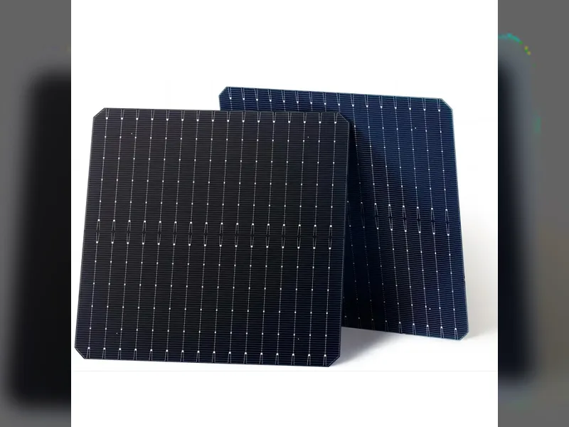
Back-contact cells move both the positive and negative electrodes to the rear, so nothing shades the front surface. TBC applies a TOPCon (high-temperature polysilicon) passivating contact across that whole rear pattern; HBC applies a heterojunction (low-temperature amorphous silicon) contact instead. HIBC does neither. It splits the rear into interdigitated N and P collection zones and gives each zone the passivation system it is best at: high-temperature polysilicon contact on the electron-collecting N zone, low-temperature amorphous silicon passivation on the hole-collecting P zone. We covered the full acronym family and where each architecture sits in the process sequence in our BC cell technology roadmap; this article focuses on what is new in the 28.29% result.
The Two Innovations That Are Actually New
The hybrid idea has been discussed for a while. What LONGi appears to have solved is the two engineering problems that stopped it working.
1. LIC — laser-induced local crystallisation
Amorphous silicon passivates beautifully but conducts poorly in the vertical direction, because it is a thin disordered film and the carriers have to cross it to reach the metal. The standard fix is a transparent conductive oxide layer, which adds cost, adds absorption, and creates its own lateral leakage path.
The HIBC answer is selective: crystallise the silicon only where the contact is actually made. A sub-micron laser treatment converts the pyramid tips at the contact points into nanocrystalline silicon, which drops the vertical contact resistance sharply, while the rest of the wafer keeps its original amorphous silicon film and therefore keeps its passivation. Critically, because only isolated points are crystallised, the lateral leakage path that would come from crystallising the whole film never forms.
This is a laser process step with tight spatial control. It is the kind of station that has to be specified with its own process window, its own alignment tolerance, and its own yield control — not bolted onto an existing tool as an option.
2. iPET — in-situ edge passivation
A finished cell is cut to size. The cut edge is a wall of dangling bonds and a recombination hotspot, and in a back-contact cell the edge sits close to both polarity regions. HIBC forms a passivation layer at the edge in situ during the process flow rather than as a separate repair step afterwards. The reported gain is roughly 1.7–3 mV of open-circuit voltage, plus better mechanical edge integrity — which matters because BC cells are already known for bowing and warpage sensitivity.
The Real Bottleneck: Two Thermal Budgets on One Wafer
Everything above has to happen on the same substrate, and that is the hard part. High-temperature steps — the ones that form and activate the polysilicon contact — run at temperatures that will destroy an amorphous silicon film. Low-temperature amorphous silicon deposition has to happen after, or the high-temperature steps have to be arranged so they never touch it.
That sequencing constraint, not the cell physics, is what makes HIBC difficult to manufacture. The reported process challenges are:
- High-temperature / low-temperature step ordering and thermal budget control
- Yield control on the laser local-crystallisation step
- Preventing the two process regimes from damaging each other’s films
A narrow process window is a manufacturing problem long before it is a laboratory problem. The record cell proves the architecture works; it does not prove the window is wide enough for a gigawatt fab.
What This Means for Module Assembly Lines
This is the part that concerns us directly, and it is worth stating plainly: a cell record does not change your module line next quarter. Cell capacity takes years to build, and HIBC is not a drop-in change to existing cell fabs. But it does tell you what the module line will be asked to handle, and it is better to plan the interfaces now than to discover them during a factory acceptance test.
Back-contact handling is a line-level capability, not a machine option
BC cells have no front busbars. Stringing, soldering and inspection therefore work on the rear surface, which changes:
- Cell handling and orientation. Every station between the cutter and the laminator has to know which side is up, and has to hold the cell without marking the front surface.
- Soldering geometry. Contact pads are on the rear and pitch is finer. Placement accuracy and temperature profile are tighter than on a conventional 5BB–20BB front-soldered cell.
- Warpage control. BC cells bow more than front-contact cells under the same thermal load, which propagates into string handling, layup placement and lamination.
- Inspection. The defects that matter on a BC string are different, so EL and VI inspection has to resolve fine rear-side features rather than front grid interruptions.
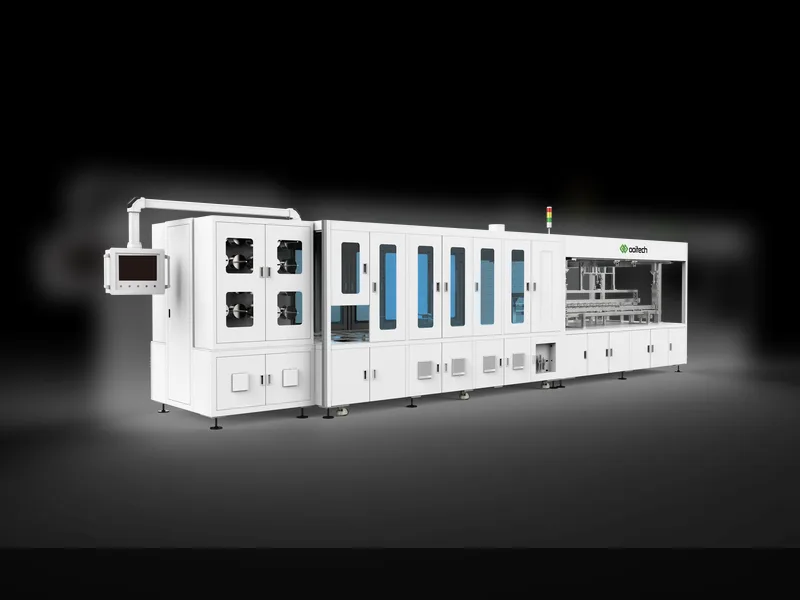
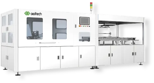
These are the stations where a line is either BC-ready or it is not. We build the specific versions for this: the SC-20P back-contact cell laser cutting platform, the OSLB-1300 back-contact cell stringer, and the SL-1000 back-contact cell welder. Every serious BC programme we have supplied has needed the same three things from the equipment side: gentler handling, tighter placement, and inspection that is tuned to the rear surface.
Why the Record Still Matters If You Buy Modules, Not Cells
Three practical consequences, in the order they are likely to reach a production floor:
- The efficiency gap between architectures keeps widening, and it is now a cell-level gap. HIBC is a hybrid of two process families, which means the efficiency ceiling is set by process integration rather than by a single architecture choice. Expect the roadmap argument to move from “which structure” to “which process window you can actually hold.”
- New cell capacity will be new-build, not retrofit. LONGi reportedly validated HIBC on a 500 MW pilot line and plans new lines rather than converting existing HPBC lines. High-temperature equipment carries over; low-temperature amorphous silicon deposition equipment does not. That is a capital cycle, and it means HIBC modules will reach the market on the timescale of new fabs.
- Module equipment procurement will be pulled forward. When a cell line is built, the module line behind it is specified at the same time. If you are planning capacity to receive BC cells, the stringer, bussing, layup and inspection stations are the long-lead items and the ones with the least tolerance for a late architecture change.
How We Would Approach It
If you are evaluating a BC or HIBC module line, the questions that decide the equipment specification are not the headline efficiency number. They are:
- Cell format and thickness, and the warp you actually measure on incoming cells
- Rear contact pad layout and pitch, and the soldering process that layout requires
- Whether the line has to run BC and TOPCon on the same equipment, and how often it changes over
- What the inspection specification is, in terms of the smallest rear-side defect that has to be caught
Answer those four and the station list follows. Ooitech builds the full module line — full automatic solar panel production line equipment, stringers, layup, bussing, laminators, framing and testing — and we have supplied BC-capable configurations for BC, IBC and HPBC programmes. If you want to check whether a line you are planning can accept a BC cell format, send us the cell drawing and the module layout and we will tell you which stations need to change.
Frequently Asked Questions
Is 28.29% a module efficiency or a cell efficiency?
Cell efficiency, measured on a laboratory cell and confirmed by ISFH. Module efficiency is always lower, because of packing losses, interconnection losses and the area taken by the frame and busbars. Do not translate a cell record directly into a module datasheet number.
Does HIBC make TBC and HBC obsolete?
Not immediately. HIBC is harder to manufacture than either, because it has to hold two thermal budgets on one wafer. TBC and HBC remain simpler process flows. The record shows the hybrid architecture has the higher ceiling, not that the simpler routes have lost their cost advantage.
Can an existing TOPCon or HPBC module line be converted to run BC cells?
Partly. The mechanical handling, layup and lamination stations are largely reusable, but the cell-facing stations — cutting, stringing, soldering and inspection — usually need BC-specific versions, because the contact geometry and the handling requirements are different. Whether a conversion makes sense depends on how much of the line is cell-facing versus panel-facing.
What is the difference between LIC and ordinary laser processing on a cell line?
Ordinary laser steps on a cell line cut, dope or ablate. LIC is a localised crystallisation step: it changes the phase of the silicon at the contact point rather than removing or adding material. That makes alignment and energy control the critical parameters, and it makes the step sensitive to anything upstream that changes the surface topography.
Where can I read the primary sources?
The efficiency result and the ISFH confirmation are reported by pv magazine and PV Tech. The process-level description of LIC and iPET comes from the industry report published by 新能供应链. Figures attributed to that report are as published there; we have not independently verified them.