From Cell to Module: The Manufacturing Process of Back-Contact (BC) Solar Modules
Table of Contents
Introduction: Why Back Contact Technology Is Reshaping the Solar Industry
The PV industry is in the middle of a real technology shift. PERC ruled for years, TOPCon rose fast, and now a third architecture is grabbing serious attention from both manufacturers and project developers: Back Contact (BC) cell technology.
Conventional front-contact cells waste a slice of sunlight because metal gridlines sit right on the sunny side. BC cells move every electrical contact to the rear. The front stays completely clean. That means higher short-circuit current, a sleeker look, and module efficiency that now competes head-on with the mainstream.
Here is the part that makes BC interesting for anyone running a line: getting from a finished BC cell to a fully assembled BC module is not the same job the industry has done for decades. No front busbars, no front fingers. That single fact changes how cells are joined, how strings are built, how ribbons are designed, and how you set your lamination recipe.
This blog walks through the full process from BC cell to BC module, step by step, with the equipment involved and the process traps you need to watch for.
1. Understanding the BC Cell: A Quick Primer
1.1 What Is a Back Contact Cell?
A Back Contact (BC) cell, sometimes called Interdigitated Back Contact (IBC) or just all-back-contact, puts both the emitter and base contacts on the rear side of the wafer in an interdigitated pattern. The front is bare silicon, which kills three things at once:
Shading losses, typically 3-5% of cell area on conventional cells
Resistive losses tied to front-grid design trade-offs
Visible gridlines, which matter a lot for looks
Leading BC variants in 2024-2025:
| Technology | Key Developer(s) | Cell Efficiency (Lab) | Cell Efficiency (Mass Production) |
|---|---|---|---|
| HPBC (High-Performance BC) | LONGi | ~26.5% | 25.0-25.5% |
| ABC (All Back Contact) | Aiko Solar | ~27.0% | 25.5-26.0% |
| TBC (TOPCon-based BC) | Multiple Chinese manufacturers | ~27.1% | 25.0-25.8% |
| HBC (HJT-based BC) | CSEM, Maxeon, Risen | ~27.1% | 24.5-25.5% |
| Classic IBC | Maxeon (formerly SunPower) | ~26.0% | 24.5-25.0% |
The direction is obvious: BC is moving from a niche premium product to a mainstream contender, pushed hard by Chinese makers scaling through 2024-2025.
1.2 The Critical Difference: Contact Geometry
On a PERC or TOPCon cell, the front busbars (9-16 on modern cells) and fingers are kept as thin as possible while still collecting current. You solder ribbon straight onto those busbars. Simple.
On a BC cell the rear side carries alternating strips of n-type and p-type contacts in a parallel, interdigitated pattern. The width, pitch and spacing of those strips are different for every maker, and they are proprietary. They also decide exactly how the cell can be interconnected inside a module.
2. The BC Module Manufacturing Process: Step by Step
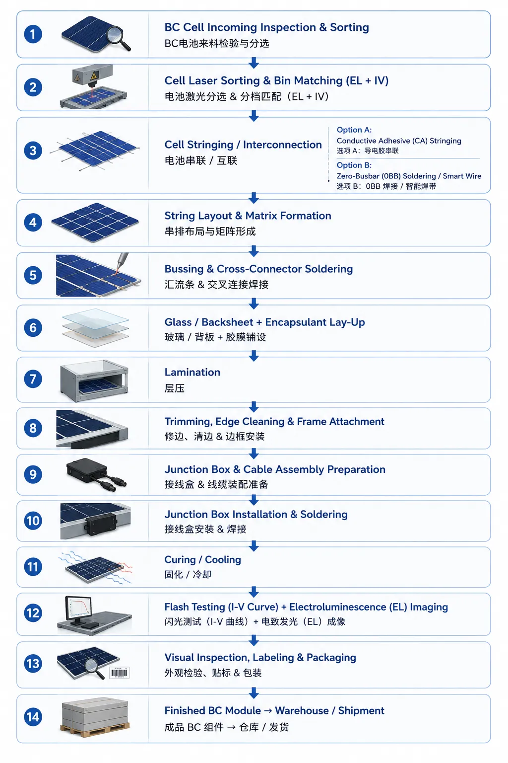
A BC module line shares plenty of gear with a conventional line, such as laminators, stringers and framing stations. But the interconnection and string-forming steps are genuinely different. Here is the full flow:
Now let's take each step in turn.
Step 1: Cell Incoming Inspection and Sorting
BC cells show up from the cell factory as quadrants, full-size or half-cut, depending on the module design. The first step matches any module line:
Visual inspection for microcracks, chipping, contamination or color variation
I-V testing for Voc, Isc, Pmax and fill factor
Electroluminescence (EL) imaging to catch microcracks, broken fingers, shunting or dead areas
Cell sorting and binning by power class, usually 1-2.5W bins, and for BC cells also by color uniformity, since the bare front makes any color drift very visible
BC-specific challenge: with no front metal, color consistency is everything, especially for residential and BIPV where looks drive the sale. Many BC makers use tighter color bins, sometimes custom-sorted with colorimeters reading Lab* values, compared with conventional modules.
Step 2: Cell Stringing / Interconnection - The Heart of BC Module Manufacturing
This is where BC modules split hardest from conventional ones, and where most of the recent equipment innovation lands.
2.1 The Interconnection Challenge
On a normal cell you solder a flat ribbon across the front busbars and fold it to the rear of the next cell. Easy geometry.
On a BC cell both the positive and negative contacts sit on the rear in an interdigitated pattern. So:
A simple front-to-back fold-over ribbon won't work
The interconnection has to bridge the rear contact strips of neighboring cells
Strip pitch, width and alignment are maker-specific
Misalignment during joining causes series resistance losses or shunting
Two interconnection approaches dominate mass production today.
Option A: Conductive Adhesive (CA) Stringing
Backed by makers like Aiko Solar for their ABC modules, this uses electrically conductive adhesive (ECA), a silver-filled epoxy, instead of solder.
Process:
A precision dispenser lays a controlled amount of conductive adhesive onto the rear contact strips
The interconnector, a flat tinned copper ribbon or a flexible printed circuit (FPC), is placed onto the adhesive
The assembly cures in a low-temperature oven, roughly 150-180C for 1-3 minutes, or during lamination
Upsides:
Low-temperature processing, so less thermal stress on cells, which matters as wafers head toward 130 microns and below
No soldering iron contact, so fewer microcracks
Fine-pitch capability down to sub-millimeter, matching the fine interdigitated pattern
The cured adhesive stays a bit flexible and soaks up thermal-cycling stress better than rigid solder
Downsides:
Silver-filled ECA is expensive
Curing adds cycle time, though inline curing during lamination helps
Long-term ECA joint reliability is still being proven at scale, though early accelerated-test data looks good
Option B: Zero-Busbar (0BB) Soldering / Smart Wire Technology
The more conventional route, used by makers like LONGi for HPBC-based modules, often with low-temperature solder or SmartWire methods.
Process:
Ultra-thin round wires, about 0.2-0.35mm, or flat wire (SmartWire) are pre-set in a carrier frame
The BC cell goes face-up, rear exposed, onto the wire assembly
A thermode (hot bar) or infrared heating briefly reflows the solder on the wire to bond it to the rear strips
The wire routes on to the next cell
The key idea is 0BB, zero busbar. Instead of soldering a thick ribbon across discrete busbars, dozens of ultra-thin wires touch the fine rear contact fingers directly, so no thick busbar is needed.
Upsides:
Builds on existing soldering gear, so lower capex
Solder joints are well understood, so reliability is strong
0BB wires conform to the interdigitated pattern
Downsides:
Needs precise thermal control, too much heat hurts thin wafers
Wire-to-contact alignment is tight and critical
Slightly higher series resistance than CA in some setups
Stringing Equipment: The Latest Generation
As of 2026-2027, leading suppliers for BC stringing include:
| Equipment Supplier | Technology | Key Feature |
|---|---|---|
| SC Solar (or Jinchen) | CA Stringing + 0BB | High-speed CA dispensing,<0.5s/cell |
| Autowell | 0BB Soldering | Multi-wire SmartWire compatible with BC |
| Leadmicro / Lead Intelligence | 0BB + CA hybrid | Flexible platform for both technologies |
| Teamtechnik (Germany) | Multi-wire stringer | Proven in Maxeon IBC production |
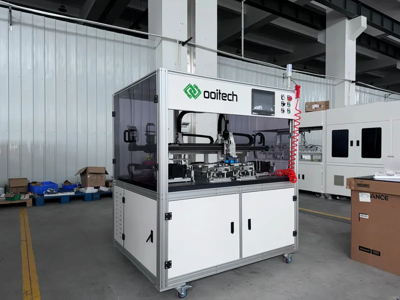
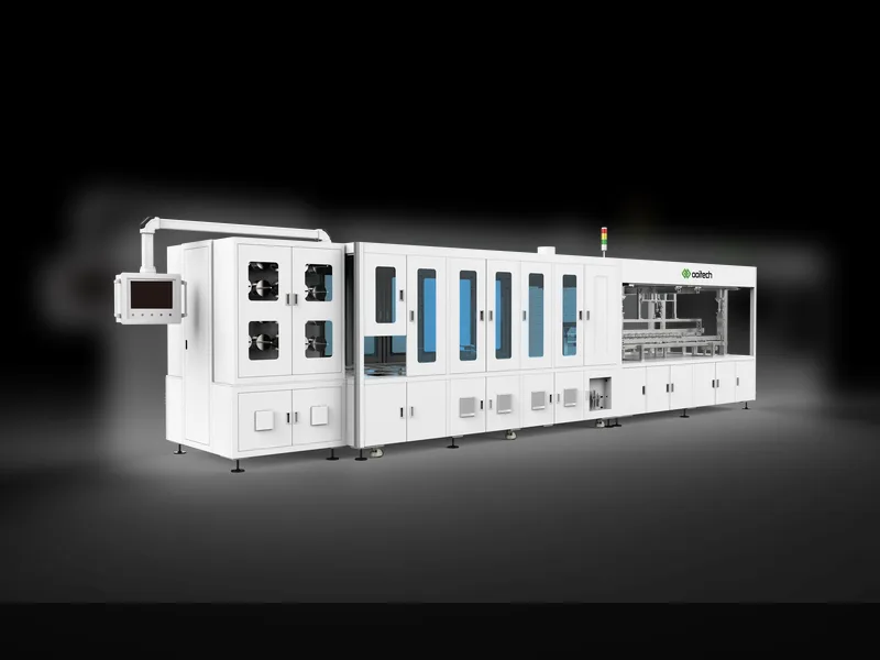
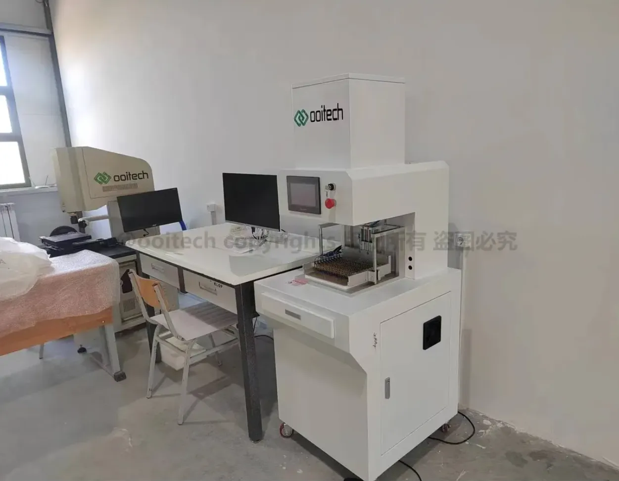
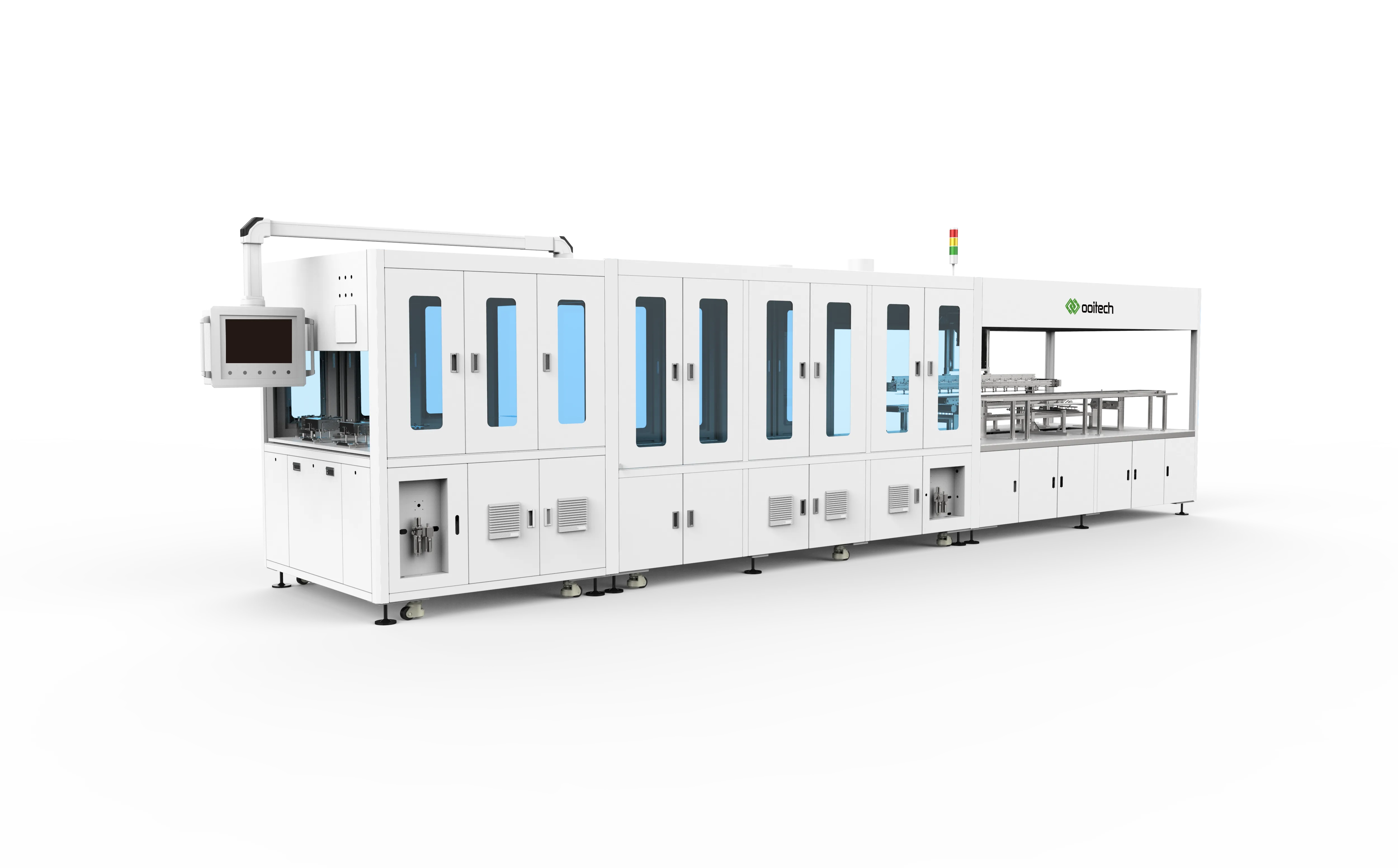
| ooitech | 0BB BC line | China BC module lines |
Stringing BC cells runs roughly 10-15% slower than conventional cells because of the tighter alignment, but suppliers are closing that gap fast.
Step 3: String Layout and Matrix Formation
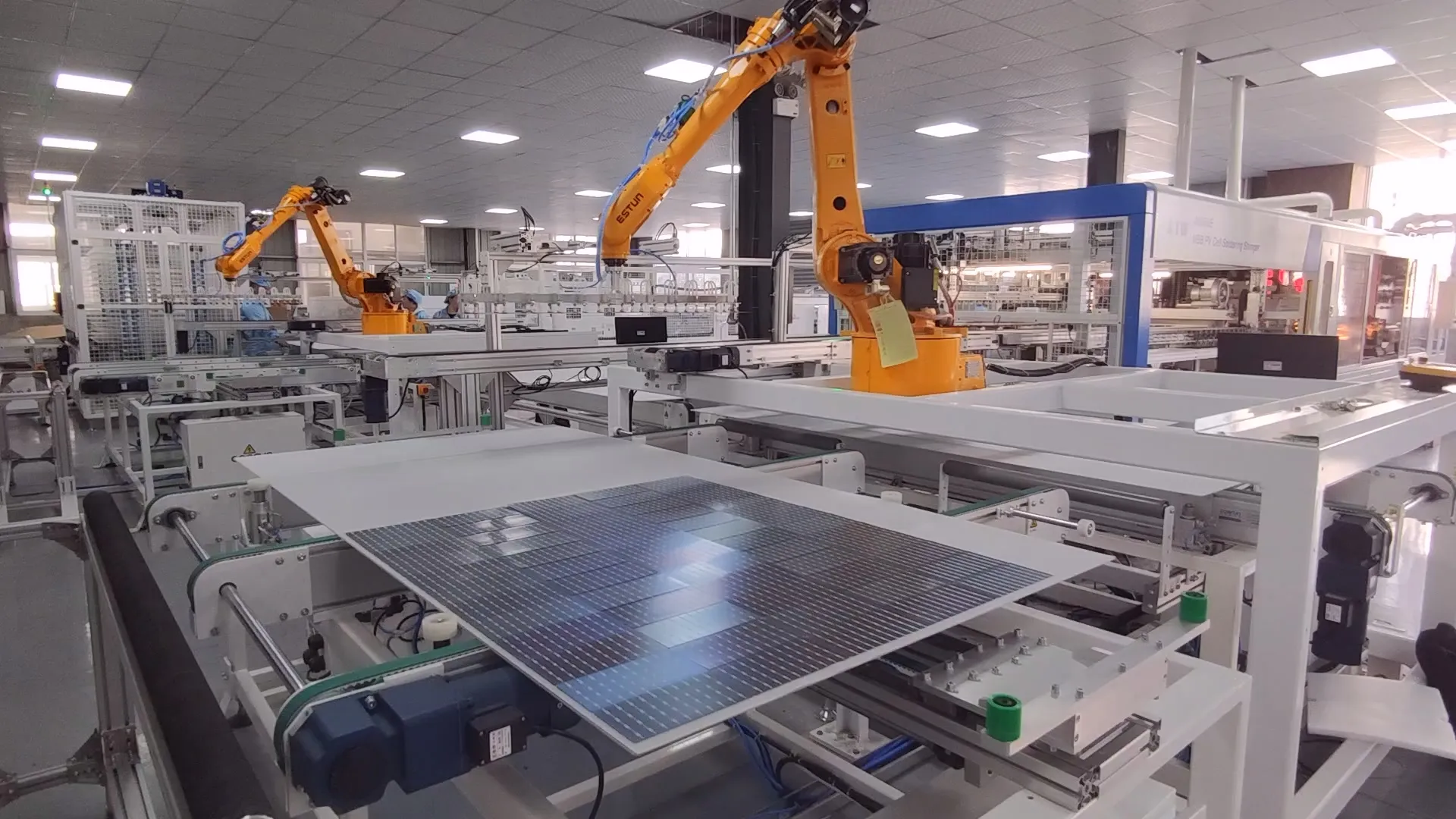
Once BC strings are formed, usually 2xN cells for half-cut layouts, they go into the module matrix:
Single-glass (glass/backsheet) or dual-glass (glass/glass), the latter increasingly common for BC targeting high reliability and BIPV
Strings are placed on the rear encapsulant in the correct series orientation
String spacing follows module size, e.g. an M10-based 72-cell module lands around 2278 x 1134 mm
BC-specific consideration: BC cells push a bit more current, thanks to zero front shading, and offer no front busbars as a visual cue. So layout usually adds an optical check to confirm cell polarity before lamination. A flipped BC cell is easier to miss than a front-contact cell with obvious busbars.
Step 4: Bussing and Cross-Connector Soldering
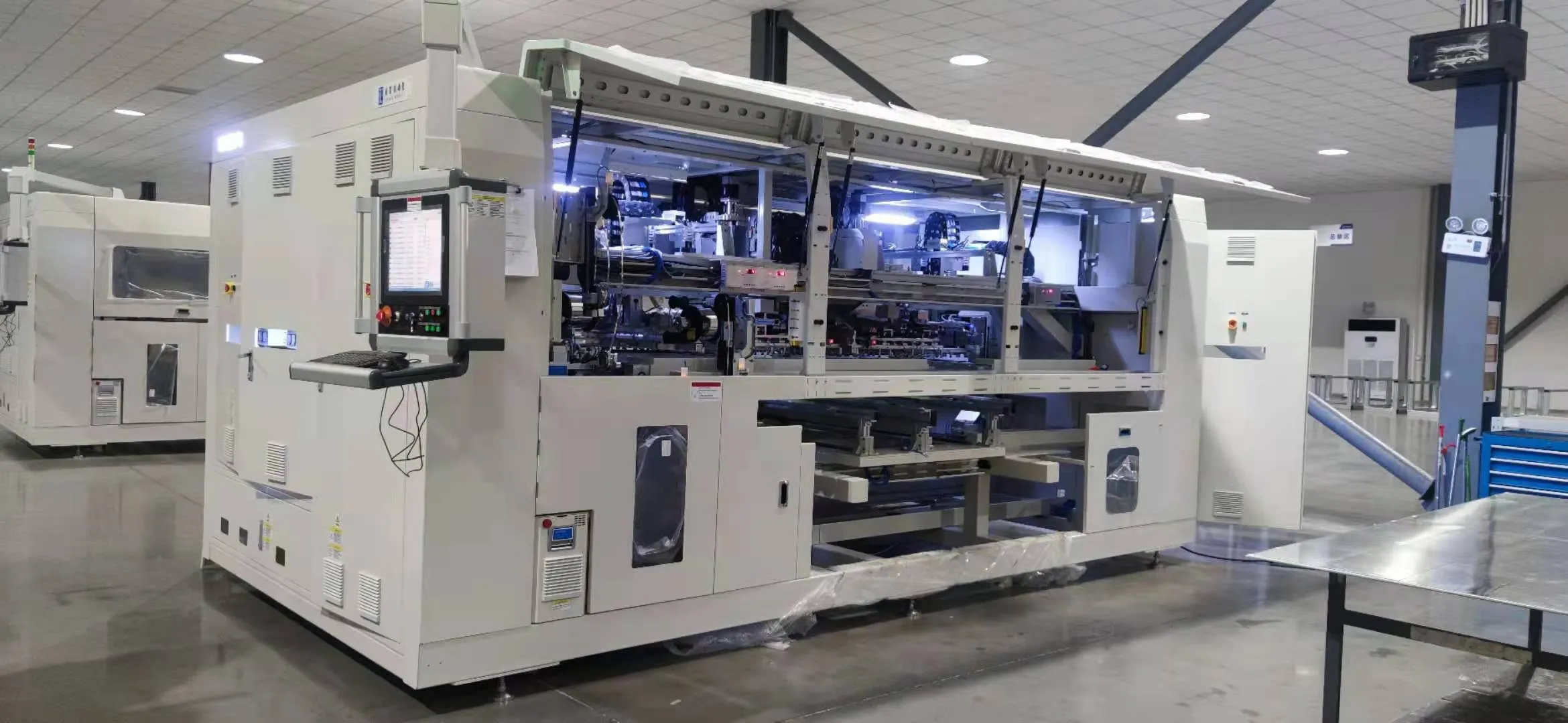
After layout, the main bus ribbons connect strings in series to build up voltage.
For BC modules:
Bus ribbon attachment follows the same principle as conventional modules, ribbon soldered to the busbar pads at the cell edge
BC cells often carry purpose-made busbar pads at the edges, wider than the fine interdigitated fingers, so bus soldering stays manageable with conventional gear
Some BC designs use integrated string connectors attached during stringing, which can drop the separate bussing step
Latest twist, shingled + BC hybrid: some makers are testing shingled BC, cutting BC cells into strips and overlapping them, so no separate bus ribbon is needed. Conductive adhesive at each overlap makes the series connection. Still niche in 2025, but promising for high-density layouts.
Step 5: Lay-Up (Encapsulant + Glass + Backsheet/Glass Assembly)
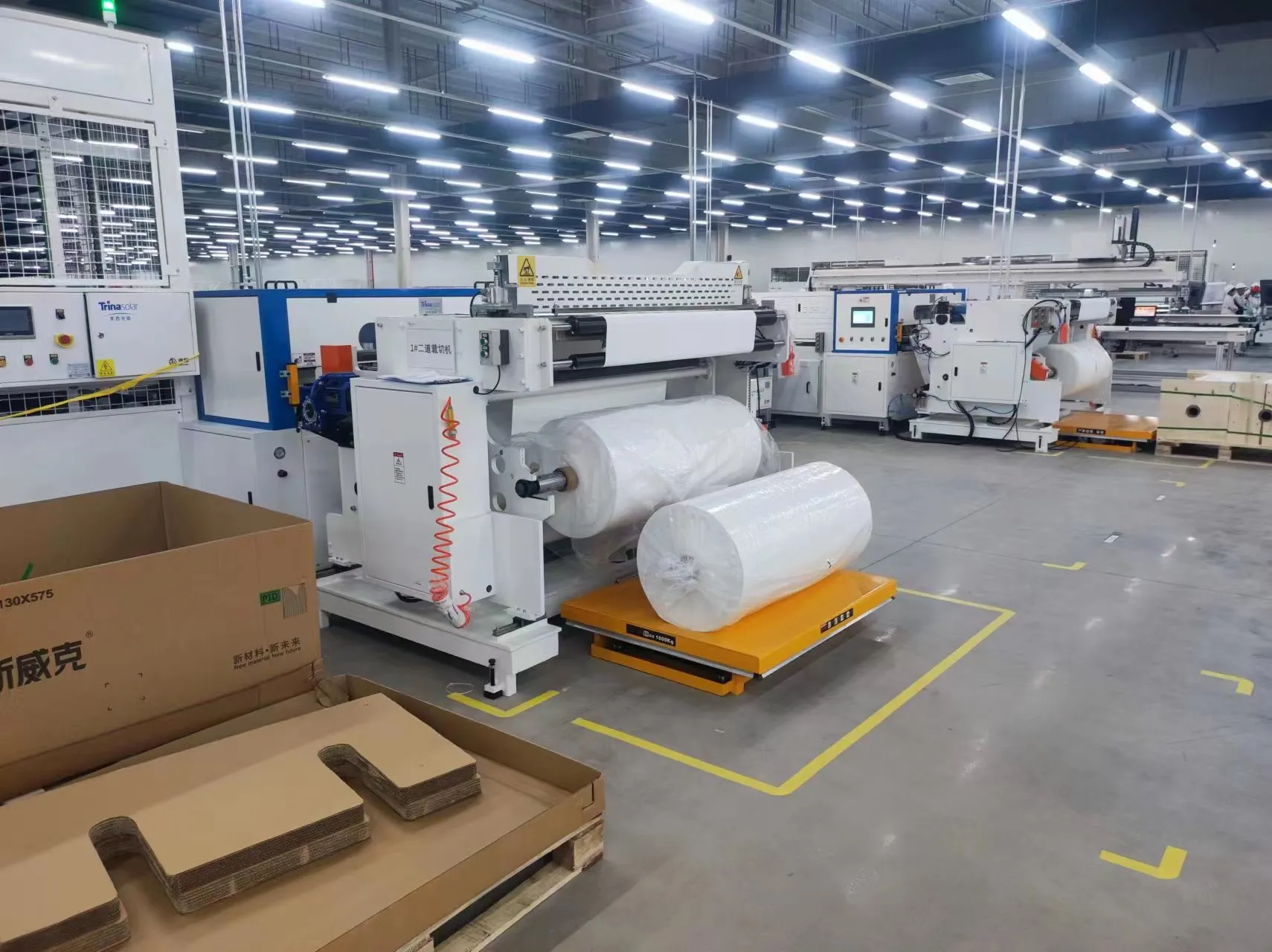
Lay-up looks a lot like a conventional module.
For a glass/backsheet BC module:
Rear encapsulant sheet, EVA or POE, 0.45-0.5mm, goes on the lay-up table
BC strings/matrix are positioned on it
Front encapsulant sheet goes over the cells
Front glass, tempered and AR-coated for max transmission, goes on top
For a glass/glass BC module, increasingly popular:
Front glass, front encapsulant, cell matrix, rear encapsulant, rear glass (transparent for bifacial gain or opaque)
BC-specific encapsulant notes:
POE (Polyolefin Elastomer) is strongly preferred over EVA for BC because of lower water vapor transmission, which protects the rear contacts from moisture corrosion; better PID resistance, which matters when the whole electrical architecture lives on the rear; and stronger adhesion to the smooth metallized rear surface
Encapsulant thickness uniformity matters more here, because uneven flow creates optical differences on the front, the show side of a BC module. Inconsistent encapsulant can leave visible bubbles or watermark defects that stand out on a busbar-free front
Step 6: Lamination
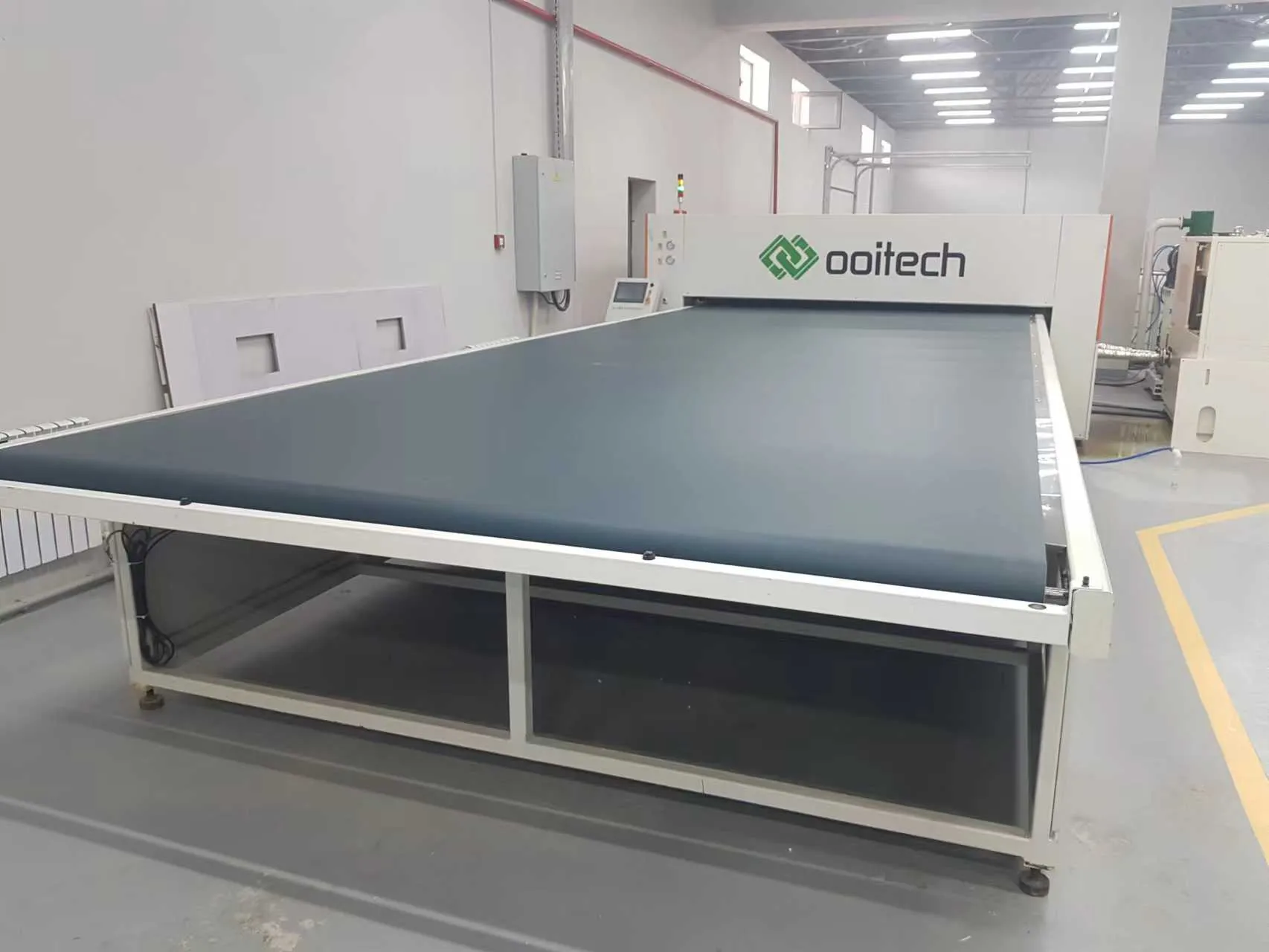
The stack heads into the laminator, arguably the most critical machine on any module line.
A typical lamination profile for BC modules:
| Phase | Temperature | Vacuum | Pressure | Duration |
|---|---|---|---|---|
| Pre-heat | 135-145C | Full vacuum (<1 mbar) | - | 3-5 min |
| Gelation | 145-150C | Full vacuum | - | 5-8 min |
| Curing / Pressing | 145-155C | Vacuum release | 0.8 atm (silicone diaphragm) | 12-18 min |
| Cooling | <80C | - | Maintain pressure | 5-10 min |
Total cycle time: 25-40 minutes depending on encapsulant and laminator.
BC-specific lamination challenges:
Air entrapment at rear contacts. The interdigitated finger pattern creates micro-topography that traps air during lamination. Top makers use textured or micro-channeled encapsulant films, sometimes called venting encapsulant, so air escapes more easily during the vacuum phases.
Curing conductive adhesive. If stringing used CA, lamination pulls double duty, encapsulating the module and curing the adhesive at the same time. The profile has to get the adhesive to full cure, roughly 150C for 10-plus minutes, without cooking the encapsulant.
Cell bow management. BC cells, especially thin ones at 140 microns or less, can bow slightly from the asymmetric stress of rear metallization. Lamination has to absorb that bow without shifting cell-to-cell spacing, so encapsulant viscosity during gelation is tuned carefully.
Laminator equipment for BC modules. The same major brands serve both conventional and BC lines, but BC-tuned laminators bring enhanced vacuum (dual-stage to<0.5 mbar), tighter temperature uniformity (about ±1.5C across the table), and programmable diaphragm pressure profiles, soft-press to full-press.
Step 7: Trimming, Edge Cleaning, and Framing
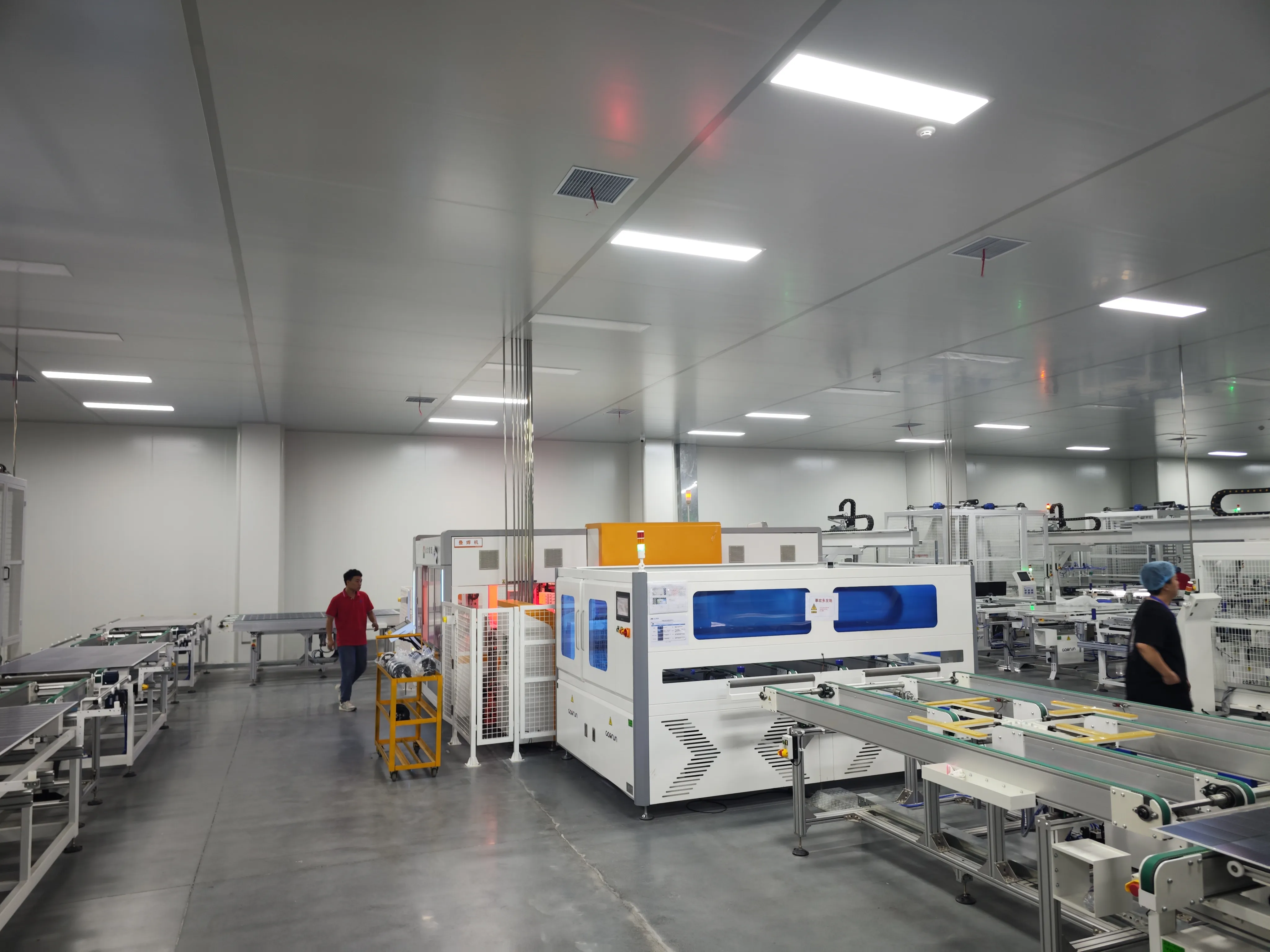
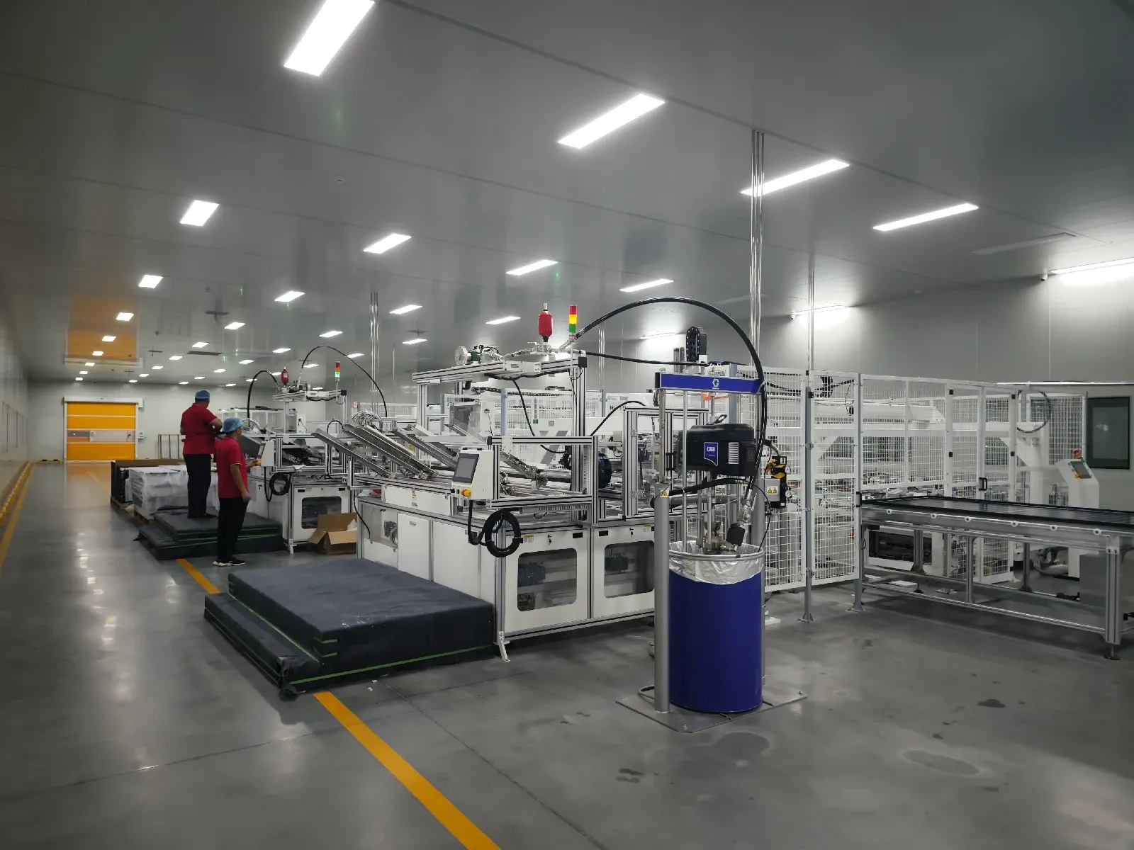
After lamination the module gets:
Edge trimming, removing encapsulant that flowed past the glass edge
Edge grinding/seaming for safety and to cut stress points
Frame attachment with silicone sealant or mechanical crimping
BC-specific framing. BC modules usually sit as premium products for residential rooftop, BIPV and high-end commercial, so frame looks count more. Black frames, anodized or painted, are standard to keep the all-black look. Some BC modules go frameless with edge sealant only, especially for BIPV. Frame profiles may be thinner or use cleaner corner joints to match the sleek cell appearance.
Step 8: Junction Box Installation
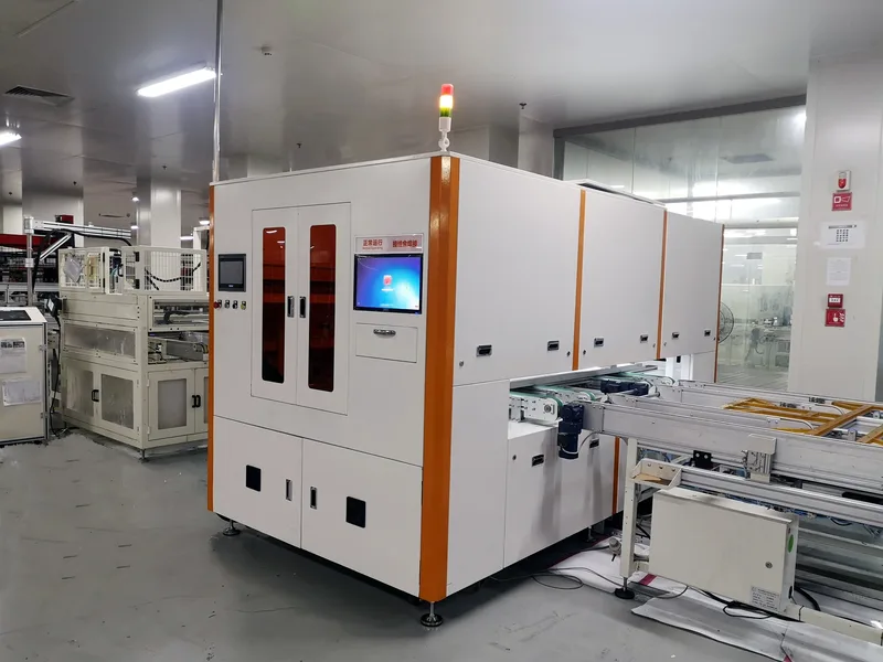
The junction box mounts on the rear and connects to the bus ribbons.
For BC modules, small-profile low-relief J-boxes are preferred, again for looks and BIPV fit. Some makers use integrated J-box designs with the bypass diodes embedded in the module rather than in an external box. Soldering or crimping the J-box leads to the bus ribbon tails is the same as on conventional modules, but leads should route away from the contact-dense rear surface to rule out any shorting.
Step 9: Curing and Cooling
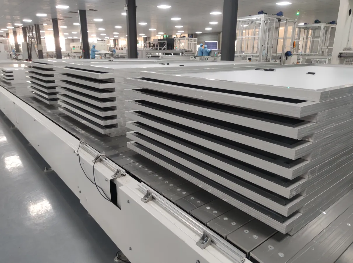
After frame and J-box:
Silicone cure: 15-30 minutes at room temperature, or faster in a warm-air tunnel at 60-80C for 5-10 minutes
Thermal conditioning: some makers run the framed module through a controlled cooling tunnel to settle the encapsulant and relieve residual stress before electrical test
Step 10: Flash Testing and Electroluminescence (EL) Imaging
The last quality gate before packing.
Flash testing (I-V curve). A solar simulator, usually AAA+ class per IEC 60904-9, fires a calibrated light pulse (AM1.5G, 1000 W/m2, 25C) and reads the full I-V curve: Pmax, Voc, Isc, FF and module-area efficiency.
BC modules routinely hit:
22.5-24.0% module efficiency for mainstream 182mm or 210mm formats
580-620W for a standard 72-cell half-cut module using M10 cells
Electroluminescence (EL) imaging. Current is injected under forward bias and an infrared camera captures the glow. Dark spots flag microcracks, broken fingers or contact strips, shunting, or dead cells.
BC-specific EL note. EL for BC modules is shot from the rear, where the contacts and current paths live. The images differ from front-cell EL, the interdigitated finger pattern shows clearly and defects look different. Operators and AI-based EL systems need BC-specific defect libraries.

Step 11: Visual Inspection, Labeling, and Packaging
Final steps:
Visual inspection for cosmetic defects, front-glass scratches, frame flaws, sealant overflow
Label with electrical data, certifications (IEC 61215, IEC 61730, MCS, UL and so on), serial number, build date
Packaging, usually 30-36 modules per pallet, with corner protectors, strapped and wrapped
Because BC modules sit at the premium end, quality tiers often go up: some makers run 100% EL inspection instead of sampling, cosmetic standards get tighter (no visible defects inside the active area), and packaging may add branded materials or installer guides for the residential audience.
3. Key Quality and Reliability Considerations for BC Modules
| Challenge | Root Cause | Mitigation |
|---|---|---|
| Rear contact corrosion | Moisture attacking metallized contacts | POE encapsulant, edge-seal designs, glass-glass build |
| Conductive adhesive degradation | Thermal-cycling fatigue of CA joints | Optimized CA formulation, stress-relief joint design |
| Cell microcracking (thin wafers) | Mechanical stress in stringing/layup | Low-stress handling, CA over solder, thinner encapsulant |
| PID (Potential-Induced Degradation) | High-voltage stress on rear junction | POE encapsulant, anti-PID cell design, grounded J-box |
| Color uniformity | Wafer variation visible on bare front | Tight incoming color binning, process consistency |
4. The State of BC Module Manufacturing in 2026-2027
The BC module market is scaling quickly:
LONGi has gone all-in on BC (HPBC 2.0) as its next mainstream technology, with announced capacity targets past 50 GW by end of 2025
Aiko Solar has ramped ABC to multi-GW scale, with mass-production cell efficiency above 25.5%
Tongwei, JinkoSolar and Risen Energy are all developing TBC (TOPCon-BC hybrid) or pure BC variants for 2025-2026 production
Maxeon keeps making premium IBC modules at its Malaysia and Mexico plants
Equipment suppliers such as Autowell, SC Solar and Leadmicro have launched dedicated BC-ready stringers and layup systems
Module-level efficiency now reaches 23.0-24.0% for commercial BC modules (single-junction silicon), with 600W-plus power classes in standard form factors.
The cost gap between BC and TOPCon modules has narrowed to roughly 0.05-0.10 yuan/Wp, under about $0.02/Wp, and many analysts expect BC to reach cost parity with TOPCon by 2026-2027 as equipment utilization climbs and silver per watt keeps falling.
5. Conclusion: BC Module Manufacturing - More Than Just a Cell Change
Building a BC module isn't just dropping BC cells into a conventional line. Interconnection, encapsulant choice, lamination recipe, inspection protocol and quality standards all need purpose-built answers that respect the geometry and the value proposition of back-contact cells.
The upside: the equipment, materials and process know-how are maturing fast. What served only the premium residential market five years ago now sits on the edge of GW-scale mainstream adoption.
For anyone weighing the BC path, the advice is simple. Nail the interconnection step first, that's where about 80% of the process work lives. Get stringing right, pick the right encapsulant, and the rest of the line is more evolution than revolution.
The era of back-contact modules is here.
Ooitech's View
We keep telling customers the same thing when they ask about BC lines: the whole game lives in the stringer and the encapsulant, not the rest of the line. Get CA dispensing repeatable and pick a good POE, and a well-built module line handles the rear-contact geometry without drama. One thing worth flagging, Ooitech supplies module (assembly) lines only, not cell production, so a BC project pairs our layup, lamination and testing equipment with whatever BC cells you source. If you want to see this flow running in a real factory, the Ooitech YouTube channel at www.youtube.com/ooitech is a good place to watch actual stringing and lamination footage.