Editorial responsibility for this article rests with Wuhan Ooi Photoelectric Technology Co., Ltd. Written and reviewed by the Ooitech editorial team. See our editorial policy for how we write, where AI tools are used, and how to request a correction.
Bypass Diode Derating: When 1.25x Isc Is Not Enough
Table of Contents
Quick answer: IEC 61215-2 pushes 1.25 times the short-circuit current through a bypass diode for an hour at 75 °C, and it is easy to read that multiplier as a safety factor. It is a site assumption: roughly 1250 W/m² of irradiance. Put the same module on a bifacial frame over fresh snow or a new white roof, add cloud-edge enhancement, and the current through that diode runs at 1.6 to 1.9 times the STC short-circuit current. Two gates decide whether it survives. Forward junction temperature is a cooling question. Thermal runaway at turn-off is a leakage question, and its boundary is far steeper than a datasheet suggests, because it depends on how fast the cloud arrives. Here is the arithmetic, the four-step derating procedure that follows from it, and the part of the problem a junction box can actually fix.
The multiplier is applied once, in a laboratory, to a module held at 75 °C. A site applies it every sunny afternoon for twenty-five years, in weather the test never sees.
What the standard does with 1.25
The procedure in MQT 18.1 of IEC 61215-2 is short. Heat the module to 75 ± 5 °C. Pass the STC short-circuit current for an hour and record the diode junction temperature. Raise the current to 1.25 times Isc for another hour. The diode then has to work normally, and the pass criterion is that the junction temperature never exceeds the maximum continuous operating temperature the diode maker publishes.
When we run MQT 18.1, we hold the module at 75 °C, dwell for one hour at the STC short-circuit current, and then increase the load to 1.25 times Isc to record diode junction temperatures.
The 1.25 is a load case, not a margin. It assumes the worst the site can do is 25 % above the STC current, which lands near 1250 W/m² of incident irradiance. For a single-faced module on ordinary ground that is a fair assumption and has been for two decades.
Bifacial modules broke it, so the 2021 edition changed the method. Power rating now uses a rear irradiance of 135 W/m², the bifacial nameplate irradiance. Any test where the stress level is set by current uses 300 W/m², the bifacial stress irradiance. The bypass diode test current becomes 1.25 times Isc at 1000 plus φ times 300, with φ the bifaciality factor. That is a better assumption than the old one. It is still an assumption, and it still answers a single question: at one presumed current, is the cooling adequate?
Three things push the current higher
The current through a conducting bypass diode is roughly the operating current of the other modules in the string, and that current tracks the total irradiance the module receives. For a bifacial module the total is the front irradiance plus φ times the rear irradiance. Three factors move that sum upward at the same time.
- A bright surface underneath. Fresh snow reflects about 0.82 of the light that reaches it, wet snow 0.55 to 0.75, a newly coated white roof about 0.7 before it weathers. The rear side of a module a metre above that surface sees a substantial fraction of the front value.
- A high bifaciality factor. Mainstream TOPCon modules sit near 0.8 and heterojunction modules higher, so the same rear light becomes more current.
- Cloud-edge enhancement. When cumulus sits near the sun, scattering from the cloud edge adds to the direct beam and ground irradiance briefly exceeds the clear-sky value. Measurements put the peak near 1450 W/m² in Finland, about 1.7 times the local clear-sky figure, 1466 W/m² in an eleven-month record from San Diego, and 1528 W/m² as an instantaneous value in southern Norway. Reports from equatorial sites exceed 1800 W/m².
Take a module with an STC short-circuit current of 18.4 A and a bifaciality factor of 0.80, and the five cases sort themselves out.
The five cases, translated
This is the comparison table from the source, with its numbers unchanged. The last column is the current expressed relative to the single-face test current of 23.0 A, which is the frame most datasheets use.
| Case | Front / rear irradiance (W/m²) | Diode current | Relative to single-face test |
|---|---|---|---|
| MQT 18, single-face | 1.25 × STC | 23.0 A | 1.00 |
| MQT 18, bifacial | 1.25 × (1000 + φ·300) | 28.5 A | 1.24 |
| White roof plus cloud edge | 1400 / 280 | 29.9 A | 1.30 |
| Snow plus cloud edge | 1400 / 420 | 31.9 A | 1.39 |
| Extreme enhancement, low latitude or altitude | 1600 / 320 | 34.2 A | 1.48 |
Two frames for the same number
The source states that a bifacial module can see 1.6 to 1.9 times the STC short-circuit current, and the table above tops out at 1.48. Both are right, and the difference is the denominator. The table divides by 23.0 A, the single-face test current. Divide by the module’s own Isc of 18.4 A instead and 29.9 A becomes 1.63, 31.9 A becomes 1.73, and 34.2 A becomes 1.86.
Keep the frames apart when you write a specification. A diode qualified at 1.48 times the single-face test current is at 1.86 times the nameplate current, and a customer reading the second number will ask why the first one was quoted.
Gate one: forward junction temperature
A conducting diode dissipates Vf times I. A Schottky part at high temperature and high current drops 0.4 to 0.5 V, so 30 A puts roughly 14 W inside a junction box a few centimetres square. All of it leaves through the box.
The steady-state estimate is as plain as the physics gets: junction temperature equals the reference temperature at the box plus the thermal resistance from junction to that reference, times Vf, times I. With a resistance of 8 K/W the two extremes separate in a way that surprises people.
Snow carries the highest current and produces the lowest junction temperature, about 150 °C, because a snowy day is cold and the box sits against a cold module on a cold roof. A white roof carries 2 A less and produces the highest, roughly 193 °C, because a summer roof with poor ventilation can hold the back of the module at 80 °C before any current flows. At 30 A that is close to the 200 °C ceiling most Schottky bypass parts publish for bypass mode, and the extreme-enhancement case goes through it.
So the worst case is not the maximum current. It is the maximum current multiplied by the maximum ambient heat, and the second half of that product is a mounting and site question that no module datasheet answers.
One caveat before moving on: this is a steady-state bound. A cloud-edge event lasts seconds to minutes and the thermal mass of the box clips the peak. Do not bank the margin on it. In broken-cloud weather the events repeat for hours, and the heat accumulates in a box that only has one way out.
Gate two: what happens at turn-off
A Schottky diode earns its place with a low forward drop. It pays for that with reverse leakage that rises exponentially with temperature, doubling roughly every 10 °C. One measurement in the literature puts the leakage increase at about 35 times between a box at 25 °C and one at 70 °C.
Now put the physics in the order the weather delivers it. Cloud-edge enhancement arrives just before the cloud itself. The diode is heated to its highest temperature by the enhanced current, and then the cloud covers the string, the mismatch disappears, and the diode turns off. It is now reverse-biased at the voltage of a substring, 12 to 13 V, while still hot from a minute ago. Reverse power, reverse voltage times leakage current, has to go somewhere.
This is where a critical temperature is worth having. For a given current and reverse voltage there is a junction temperature at which reverse power equals forward power. Below it, the diode cools after turn-off. Above it, the leakage doubles as the junction heats, which raises the reverse power, which heats it further, and the part runs away to a short-circuit failure. That critical temperature depends on the forward drop and the leakage curve of the diode. It does not depend on the thermal resistance of the box, which is why a better box does not move it.
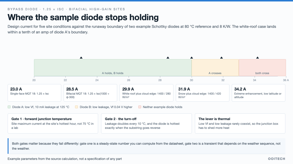
Two example parts show the trade-off. Part A has the lower forward drop and the larger leakage, and its runaway boundary sits near 30 A at 80 °C reference and 8 K/W, within a tenth of an amp of the white-roof case. Part B has lower leakage and a boundary near 33 A, but its forward drop is 0.04 V higher, so at 30 A its forward junction temperature already passes 200 °C and it fails gate one first. Low forward drop and low leakage are hard to buy together, which is the honest reason this problem is not solved by changing the diode alone.
The transient is steeper still. Take part A through ten cycles of sixty seconds of enhancement and thirty seconds of fall, the pattern of a broken-cloud afternoon, then shade the whole string. At 8 K/W and 80 °C it cools off after turn-off and stays safe. Raise the thermal resistance to 10 K/W and the ambient by 5 K, and the junction crosses the critical point in the second after the shade arrives.
When we test this transient profile, we cycle the diode through sixty seconds of high current and thirty seconds of fall at an 80 °C reference, verifying that thermal resistance stays at 8 K/W rather than 10 K/W.
The same picture, drawn as current
Five site conditions, two example Schottky diodes, one reference temperature of 80 °C and one thermal resistance of 8 K/W. The white-roof case lands within a tenth of an amp of the first diode’s boundary.
Read the figure as a specification review. Every site case to the left of a diode’s boundary is a case that diode can survive on the given thermal design. Everything to the right is a case where the datasheet number was met and the site was not.
Four steps to a derating number
The method the source proposes turns the two gates into a design procedure. It takes an afternoon with a simulator once the site is known.
| Step | What to do | The number to write down |
|---|---|---|
| 1. Fix the design current | Take the site maximum front irradiance, 1400 to 1500 W/m² for most projects and higher at low latitude or altitude, then the rear irradiance implied by albedo and mounting height. Compute I = Isc × (G front + φ × G rear) / 1000, then add a binning and process margin. | The current the box must carry, which is not the STC current |
| 2. Check forward temperature | Use the site maximum reference temperature, roof projects separately. Require the junction to stay 25 K below the part’s bypass-mode maximum. | At 30 A and 80 °C, 6.7 K/W or better |
| 3. Check the critical temperature | Read the high-temperature leakage curve from the datasheet, convert it from the rated voltage (often 45 V) to the actual substring voltage, and find the temperature where reverse power equals forward power. | Forward junction at least 15 to 20 K below that temperature |
| 4. Verify at the design current | Run MQT 18 and IEC 62979 at the current from step one rather than the standard default. | A margin in amps and kelvin, not a pass or fail |
What the line can change, and what it cannot
The site decides the albedo, the latitude and whether the roof is white. Those are inputs. What a module maker and a box supplier decide together is the thermal path and the part: split junction boxes so the heat from three substrings does not stack in one potting cup, larger copper or heat-sink area, higher thermal conductivity in the potting compound, box position on the backsheet where the module runs cooler, or an active bypass element that drops the forward voltage to tens of millivolts.
The assembly step matters in a way that shows up at exactly the wrong moment. A cold or voided solder joint at the box tab, the failure mode behind a good number of field burnouts, adds local resistance next to the diode, which raises the reference temperature that both gates depend on. Potting coverage from the filling station and the weld quality from the box soldering station set the thermal resistance that no datasheet quotes, because it is yours.
Two honest limits. You cannot test your way out of a box that is undersized for the site; the test runs at whatever current you choose, and choosing the standard default is how a snowy project passes qualification and fails in year three. And you cannot fix a wide distribution with a better champion part, which is the same lesson that the qualification standards teach about every other failure mode.
Where these numbers come from
The standard clauses, the irradiance measurements, the threshold temperatures and the four-step method come from a Chinese-language technical article on bypass diodes in bifacial high-gain conditions, published in October 2026, which cites IEC 61215-1 and -2 (2021), IEC 62979:2017, and papers by Lappalainen and Kleissl, Yordanov, Shiradkar and others, plus an Energies paper on leakage under high box temperature. The albedo values trace to a simulation tool’s reference table.
The worked example uses illustrative parameters, and the source says so: forward drop approximated as 0.28 plus 0.0065 times I with an extra 0.04 V for the second part, junction-to-box 8 K/W, a two-node thermal network of 2 K/W and 1 J/K at the junction and 6 K/W and 100 J/K at the box, leakage of 10 mA and 2 mA at 125 °C and 12.5 V doubling per 10 K, rear irradiance at 20 % of front for a white roof and 30 % for snow, and no temperature coefficient on the short-circuit current, about a 1 % effect. No commercial part is described. We have not re-derived the numbers; the method is what we would import into a specification review, and the measurements are what you would take on your own box.
One thing we would add. The paper on why shading does not always create a hot spot covers the cell-level mechanism this article takes for granted: the shaded cell goes into reverse bias and dissipates, and the diode exists to short that substring out before the cell is damaged. The diode is the protection, and a diode that runs away at turn-off is a protection that has stopped working while the module looks fine on a curve tracer.
Frequently asked questions
Is 1.25 times Isc a safety factor?
It is an irradiance assumption, near 1250 W/m². On a single-faced module over ordinary ground it holds. On a bifacial module over snow or a bright roof with cloud-edge enhancement, the site current runs well above it.
What did the 2021 edition change for bifacial modules?
Power rating moved to a rear irradiance of 135 W/m², and current-driven stress tests moved to 300 W/m². The bypass diode test current became 1.25 times Isc at 1000 plus φ times 300, which is 28.5 A in the worked example, still short of the white-roof and snow cases.
Which is worse, snow or a white roof?
The white roof, in the summer. Snow delivers the higher current on a cold day and lands near 150 °C. A white roof delivers less current on a day when the box behind the module is already at 80 °C, and the junction estimate reaches about 193 °C.
What is the critical temperature?
For a given current and reverse voltage, it is the junction temperature at which reverse leakage power equals forward power. Below it the diode cools after turn-off. Above it the leakage raises the temperature, which raises the leakage. It depends on the diode, not on the thermal resistance of the box.
Why does the failure happen at turn-off rather than at peak current?
Because the diode is hottest exactly when the substring goes reverse-biased. Cloud-edge enhancement heats it, the cloud arrives, mismatch disappears, and the part is asked to hold a substring voltage with a junction temperature near its maximum.
Can a lower forward drop fix it?
Usually the opposite: the parts with the lowest forward drop tend to have the higher leakage, and their runaway boundary arrives earlier. In the example, the low-drop part crosses at 30 A while the low-leakage part crosses at 33 A but fails the forward-temperature gate first.
What test covers thermal runaway?
IEC 62979 is written for this process. Diodes with a P/N junction and adequate reverse tolerance can be exempted. It is worth running it at your design current rather than the default, because the default is the assumption under discussion.
What should go into a purchase specification?
A design current from the site, a thermal resistance target such as 6.7 K/W at 30 A and 80 °C, a forward junction margin of 25 K below the bypass-mode maximum, a critical-temperature margin of 15 to 20 K, and a verification run at the design current rather than the standard one.
Final thoughts
A bypass diode is chosen once and lives through twenty-five years of weather it was never tested in. The multiplier in the standard describes a site, not a margin, and the two gates that decide the outcome are a cooling number you can compute and a leakage number most datasheets bury. Specify both, and test at the current your site will actually apply. The most dangerous day is rarely the brightest one. It is the bright, hot day with broken cloud moving across, which is also the day nobody is looking at the junction box.
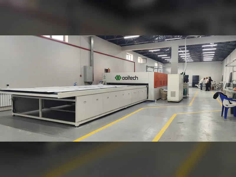
To build reliable bifacial modules that withstand high thermal loads, OOITech supplies solar panel laminator machines in single and double chamber configurations with oil-heated or electric heating platens. Send us your module drawings, your current module stack, or production samples for technical evaluation and lamination process testing.