Editorial responsibility for this article rests with Wuhan Ooi Photoelectric Technology Co., Ltd. Written and reviewed by the Ooitech editorial team. See our editorial policy for how we write, where AI tools are used, and how to request a correction.
TOPCon vs BC Solar Cells: A Backside Comparison
Table of Contents
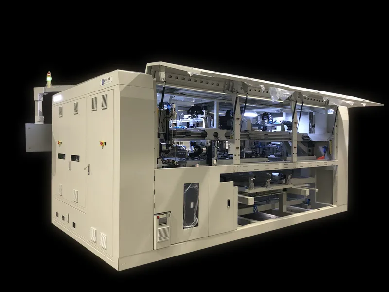
Quick answer: The difference between TOPCon and back-contact is usually argued on the front of the cell, where it can be measured, but most of the real difference sits on the back. TOPCon keeps a front busbar and uses a passivating contact on the rear; back-contact moves both polarity contacts to the rear and removes the front busbar entirely, which frees the whole front surface for light but makes the rear pattern much denser. That rear density is what changes the manufacturing: a BC line needs insulating glue between opposite-polarity joints, tighter tooling at the stringer, and rear-side inspection that a TOPCon line does not require in the same way. Machines in the SS-1500B class serve TOPCon, while BC needs the dedicated rear-contact tooling. The efficiency argument on the front is real; the cost argument is on the back.
The difference between TOPCon and BC is usually argued on the front of the cell, where you can measure it. Most of the manufacturing risk sits on the back, where you have to look for it.
PV Cell Technology · Module Manufacturing · by Jerry, Ooitech
1. The Comparison, in One Photograph
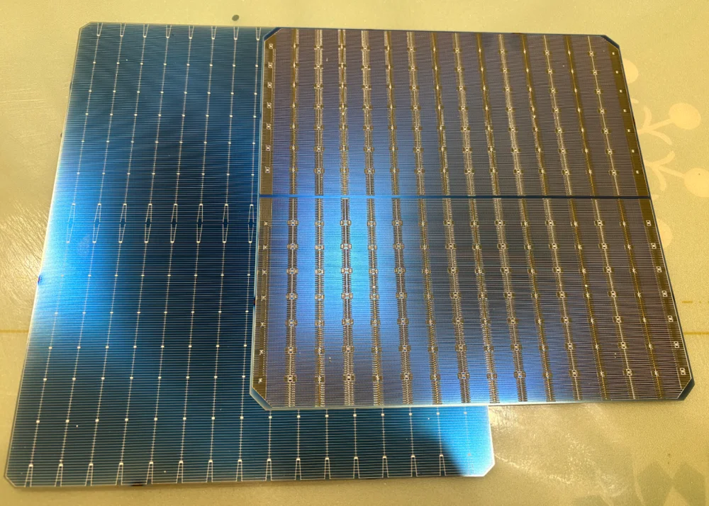
Fig. 1: A TOPCon cell backside (left) beside a BC cell backside (right). The TOPCon rear surface is a continuous, largely uniform field. The BC rear is organised into discrete electrode zones.
The left cell shows what a conventional rear structure looks like: a broad, even field with a single family of features running across it. The right cell is doing something structurally different. Both the positive and the negative electrodes live on that one surface, which is why the pattern is denser and more segmented.
That single observation explains the trade-off that follows BC through every stage of module manufacturing.
2. Why BC Buys Front Efficiency With Bifaciality
BC moves both polarities to the rear. The front of the cell therefore carries no busbars and no fingers, so no metal blocks incoming light and no shading losses are paid at the front. That is the source of BC's front-side efficiency advantage, and it is a real one.
The cost is paid on the back. Because all the metallisation is concentrated on one surface, the rear of a BC cell is crowded with fine fingers and busbars. Those metal lines occupy area that would otherwise collect rear-side irradiance, so a BC module collects less light from behind than a TOPCon module of the same format. This is the structural reason BC bifaciality sits below TOPCon bifaciality, and no amount of process tuning removes it. It is a design consequence, not a defect.
| TOPCon | BC | |
|---|---|---|
| Electrode placement | Opposite polarities on opposite faces | Both polarities on the rear face |
| Front shading | Fingers and busbars shade the front | No front metallisation, so no front shading |
| Rear light collection | Rear is largely free of metallisation | Rear metallisation reduces the collecting area |
| Extra process step | None specific to polarity isolation | Insulating material between opposite-polarity electrodes |
3. The Electrode Layout Problem
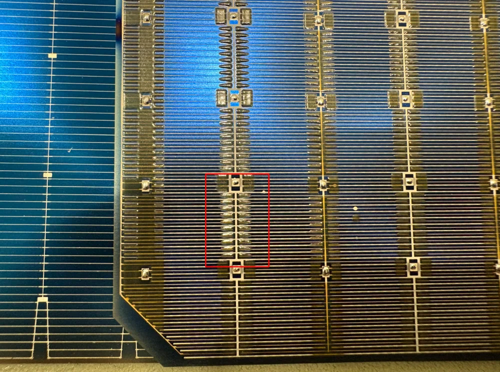
Fig. 2: A closer view of the BC rear. The highlighted region sits where opposite-polarity structures run close together, which is precisely where isolation has to hold.
On a TOPCon rear, the polarities never meet, because they are on different faces of the cell. On a BC rear they share one surface, arranged in zones: negative fingers, negative busbars, positive fingers and positive busbars, all interleaved across the same plane.
That adjacency is the engineering problem. Two electrodes of opposite polarity sitting a short distance apart will short the cell if they ever come into contact, whether through a printing defect, a soldering excursion, contamination, or mechanical damage during handling. The insulating material printed between them is what prevents that, which makes it a functional layer rather than a protective extra.
We cover the material and process side of this in detail in why BC solar cells need insulating glue on the back, including what the layer has to do and how it is applied.
4. The Question Nobody Can Answer With a Lab Test
Once the isolation depends on a printed layer, the obvious question is how long that layer lasts. A module warranty runs 25 years, and the field environment is not gentle: daily temperature swings, sustained ultraviolet exposure, moisture ingress and repeated thermal cycling all act on the same interface.
The isolation layer has to stay isolating for that entire period. It cannot crack, chalk, delaminate or degrade into a conductive path. A freshly made cell that passes incoming inspection proves the layer was correctly applied on the day it was tested. It does not prove anything about year twelve.
This is the substance of the long-term reliability debate around BC, and it is a fair debate rather than a criticism. Three variables decide the outcome:
| Variable | Why it matters |
|---|---|
| Material formulation | Weathering resistance is a property of the chemistry. Two suppliers selling "insulating glue" can be years apart in UV and damp-heat performance. |
| Coating control | Thickness uniformity and edge definition decide whether the isolation is continuous. A thin or interrupted print is a latent short. |
| Curing | Under-cured material keeps reactive components and loses adhesion; over-curing embrittles it. Both shorten field life. |
This is where suppliers separate. Manufacturers using high-weathering formulations with tight print and cure control are buying margin against the 25-year question. Manufacturers who treat the isolation layer as a cost line to be minimised are carrying a risk that will not appear until the modules are in the field and out of warranty reach.
5. What This Changes on a Module Line
For a factory assembling BC modules, the rear architecture changes four things on the floor.
| Area | What changes |
|---|---|
| Stringing | All interconnects land on one face. Placement tolerance and soldering temperature control matter more, because a soldering excursion near the isolation layer does damage that is not visible optically. |
| Mechanical stress | Heating one face of a cell while the other stays cooler produces bowing. BC strings and modules are more sensitive to this, which is covered in why BC cell strings warp like a boat and why BC cells are more prone to bowing. |
| Inspection | A short between adjacent electrodes may not show as a mechanical defect. EL imaging reveals the electrical consequence, and it needs to be read with knowledge of where the polarities run. |
| Traceability | Because the failure mode is latent rather than immediate, per-module test records are the only way to answer a field claim years later. |
None of this makes BC harder to manufacture in absolute terms. It makes the process window narrower in specific, identifiable places, and it raises the cost of inconsistency. That has a direct equipment consequence: a line running BC formats needs soldering control and inspection capability sized for a narrower window than the same line running TOPCon.
6. How to Reduce the Risk
Four practical measures, in the order they pay back.
- Qualify the isolation material, not the supplier. Ask for UV and damp-heat data on the specific formulation, not a general "anti-PID" or "insulating" claim. Compare formulations across the range you might use, including any planned second source.
- Control print and cure as process parameters. Thickness uniformity, edge definition and cure schedule belong in the process control plan with limits and records, because the failure they prevent is invisible at the station.
- Inspect electrically, not only optically. EL imaging after stringing and after lamination, paired with an I-V measurement per module barcode, is what turns a latent risk into a detectable one. The reasons EL is the right tool are set out in EL testing: inline vs offline setup.
- Match the stringer to the format. BC interconnects are all on one face, so soldering-head configuration, ribbon handling and temperature profile are format-specific. Our SS-1500B tabber stringer is specified to cover BC, TOPCon and PERC cells for exactly this reason, and we have delivered BC stringing capacity to European manufacturers including a Polish module manufacturer.
7. FAQ
Why is BC bifaciality lower than TOPCon?
Because both electrodes are on the rear. The rear metallisation occupies area that would otherwise collect rear-side irradiance, so less light reaches the cell from behind. TOPCon keeps the two polarities on opposite faces, leaving the rear comparatively open. It is a structural consequence of the architecture, not a manufacturing quality difference.
What is the insulating layer on a BC cell for?
It isolates the positive and negative electrodes that share the rear surface. Without it, any contact between adjacent opposite-polarity structures shorts the cell. It is a functional layer, not an optional coating.
Can the 25-year reliability of that layer be proven?
Not directly. Accelerated tests and incoming inspection demonstrate that the layer was correctly applied and specified. Whether it stays isolating for 25 years depends on formulation, print uniformity and cure, and on how those hold up under UV, moisture and thermal cycling. That is why the material specification and the process records matter as much as the incoming test result.
Does BC need different equipment from TOPCon?
Not different machines, but different settings and tighter control in specific places: soldering temperature and head configuration, handling that avoids one-sided heating, and inspection that can detect an electrical fault with no visible mechanical signature. Many stringer platforms cover both formats when configured correctly.
Does the rear metallisation pattern affect EL inspection?
It changes how you read the image. A short or an interrupted region on a BC rear does not always correspond to an obvious visual defect, so the operator needs to know where the polarities run and what a normal rear looks like before judging an anomaly. Reference images by cell format are worth keeping at the station.
Which format should a new module factory choose?
It depends on where the modules will be installed. TOPCon's higher bifaciality favours ground-mounted and elevated installations where rear irradiance is meaningful. BC's front-side efficiency favours area-constrained applications such as rooftops, where packing more power onto a fixed roof area matters more than rear gain. The right answer is a function of the installation, not of the module alone.
Final Thoughts
The backside photograph makes the BC trade-off legible in a way a datasheet does not. Moving both polarities to the rear buys front-side efficiency and costs bifaciality, and it introduces a printed isolation layer whose long-term behaviour cannot be proven in a lab. For a module factory that means three things to get right: qualify the isolation material specifically, control print and cure as process parameters with records, and inspect electrically so a latent fault becomes a detected one. If you are configuring a line for BC or TOPCon formats, tell us the cell format, ribbon specification and target module size, and we will specify the stringing and inspection configuration around it.
Related: Hybrid contact BC cells: what 28% still has to prove — the rear-face comparison this architecture departs from.
Further reading and background data
Public reference material on this topic, published by the organisations that maintain the industry's technology roadmap and market data: