Snail Trails on Solar Panels: Causes and Prevention
Table of Contents
Snail Trails on Solar Panels: Causes and Prevention
A grey or yellow-brown line appears along a cell crack months after installation, and the module gets blamed. Snail trails are usually cosmetic. The crack underneath is not. On a module line, the crack is the part you control.
PV Module Manufacturing · Module Reliability & Inspection · by Jerry, Ooitech
1. What a Snail Trail Is, and What It Is Not
A snail trail, also called a snail track or worm mark, is a grey, yellow-brown or dark discolouration on the front of a crystalline-silicon module. It usually follows a silver grid finger, a cell edge, or the path of a cell crack. That last pattern is where the name comes from: the discolouration traces the crack the way a trail crosses glass.
IEA PVPS, the international collaborative programme on photovoltaic power systems, describes a snail track as discolouration of the front metallization and reports that it typically becomes visible roughly three months to one year after installation. The timing varies with module design and with the operating environment, which is why two identical-looking installations can diverge.
The distinction that decides most commercial arguments is this: the visible trail and the underlying electrical defect are not the same thing. Current IEA PVPS guidance states that snail tracks themselves have no demonstrated direct influence on module performance. What can reduce output or create abnormal heating is an associated condition: a cell crack that separates an active region, a damaged grid finger, a faulty interconnect, or current mismatch inside a substring.
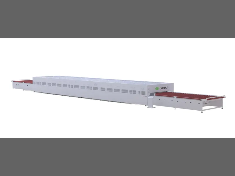
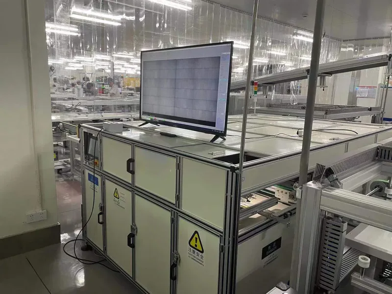
Fig. 1: An inline EL inspection station on a module line. The monitor shows the electroluminescence image, where a crack appears as a dark line. A snail trail observed in the field often follows exactly that line.
| A snail trail is | A snail trail is not |
|---|---|
| Discolouration of the front metallization, visible to the eye | Proof that the module has lost power |
| A pattern that usually follows a crack, cell edge or grid finger | Proof that the crack was made on your production line |
| Evidence that a pathway and a chemistry were both present | The same failure mode as PID, LID or LeTID |
| Often slow to develop and often stable once formed | An automatic reason to reject a shipment |
2. How a Snail Trail Forms: Crack, Chemistry and Transport
No single cause produces a snail trail. The published evidence points to an interaction, and three conditions have to overlap before anything becomes visible.
| Condition | What it means on a module | What you can influence |
|---|---|---|
| A pathway | A microcrack, a cell edge, or a gap between cells that lets species move along the metallization | Cell handling, cutting, stringing, lay-up, lamination and framing loads |
| A chemistry | Silver metallization reacting with reactive species to form discoloured silver compounds | Encapsulant and backsheet formulation, and their additives |
| Transport | Gases and volatile products moving through the polymer layers, plus UV and temperature driving the reaction | Barrier properties of the laminate and the bill of materials as a system |
The chemical evidence is more specific than the popular explanation. Microscopy and chemical studies have linked snail-trail discolouration to changes in the silver metallization system. Meyer and co-workers identified silver nanoparticles in the encapsulant immediately above affected grid fingers. Peng and co-workers identified silver carbonate nanoparticles on discoloured silver grids. Other investigations have reported silver acetate, silver phosphate, silver carbonate and silver sulfide on field-exposed modules. Fan and co-workers identified silver acetate and proposed a mechanism involving the silver grid, oxygen and acetic acid near a microcrack.
Those findings do not add up to one universal pathway, and that matters for how you specify materials. The term "snail trail" describes visually similar discolouration that more than one material interaction can produce.
One result in particular should change how you read supplier claims. Fan and co-workers modelled the process and ran accelerated tests. In their results, a microcrack together with a cell gap acted as a transport pathway. Oxygen transmission through the backsheet had an important influence on silver-acetate formation. Within the water-vapour transmission range examined in that study, water-vapour transmission was not found to control snail-trail formation.
A crack is a common precondition for a crack-aligned trail, but it is not sufficient. Many cracked cells never develop a visible trail. IEA PVPS identifies the combination of module materials, UV radiation and temperature as an important reason why susceptibility differs between module designs.
3. Snail Trail, PID and LID: Three Aging Modes, Three Clauses
These three terms get mixed together in specification documents, and the mix-up is expensive. They have different drivers, different evidence, and different test clauses. Writing one general "no degradation" clause covers none of them properly.
| Snail trail | PID | LID / LeTID | |
|---|---|---|---|
| Main driver | A pathway plus silver metallization chemistry, with oxygen transport, UV and temperature | System voltage combined with humidity and temperature, driving ion migration and shunting | Bulk silicon and hydrogen-related defect kinetics under illumination and heat |
| How it shows | Visible discolouration following a crack, grid finger or cell edge | Power loss and shunting, frequently weighted toward cell edges near the frame | Power loss without a characteristic visible pattern |
| In the EL image | Often coincides with a crack; inactive regions where the crack separates active area | Dark, often edge-weighted regions affecting many cells | Gradual loss of contrast rather than one localised pattern |
| Evidence to ask for | Visual record plus EL image plus I-V curve against a baseline | Damp-heat and voltage-stress test data under IEC TS 62804 | Illuminated soak and dark-storage measurement on the cell type you are buying |
For LID and LeTID specifically, the behaviour is cell-technology dependent and cannot be transferred from one cell type to another. Our own measurements on back-contact n-type cells tie the steady-state temperature coefficient, the LeTID dynamics and dark leakage together, and the conclusion is explicitly limited to the measured cell rather than to the technology family. If you buy a different cell, you need that cell's data. We cover the measurement approach in more detail in the temperature degradation and LeTID study on n-type back-contact cells.
For PID, the anti-degradation performance of the encapsulant is normally quoted against IEC TS 62804, and the encapsulant comparison on this site lists that parameter for each film type. That is the right place to anchor a PID clause, because the failure is driven by the electrical and moisture environment the encapsulant has to survive.
4. Where Your Line Creates the Precondition: Cell Cracks
A snail trail needs a pathway. On the manufacturing side, that pathway is a crack, and cracks come from a short list of places. IEA PVPS identifies cell handling, cutting, stringing, soldering, lay-up, lamination, framing and local mechanical pressure as potential sources, and adds packaging, transport and installation as major post-production sources.
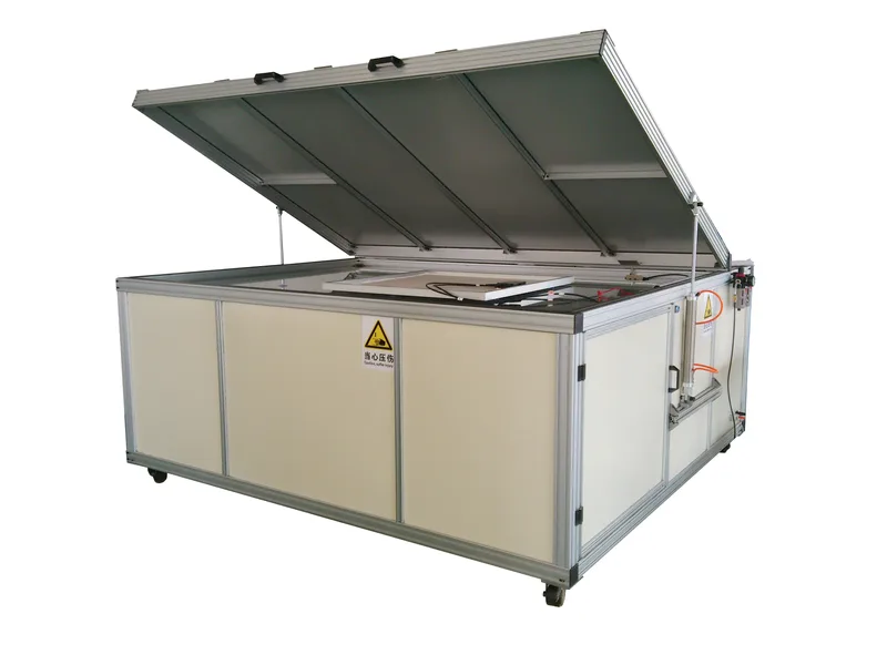
Fig. 2: A module laminator with the chamber open. Lamination applies heat and pressure to the whole laminate, so any crack present at lay-up is carried into the finished module and is no longer cheap to remove.
Two operational signals are worth watching. First, repetitive crack patterns across multiple modules usually indicate a production-related mechanism rather than random handling damage. Second, crack appearance alone does not identify the event that caused it, so the useful question is not "is there a crack" but "at which stage did it appear".
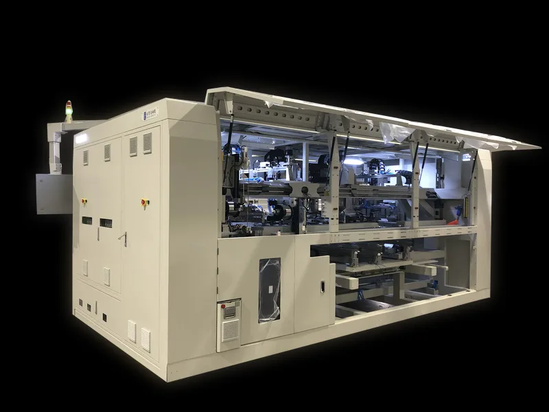
That question is answerable if you inspect at more than one point. Ooitech builds EL inspection for three positions on the line, and the specification differences between them are what let you localise a crack instead of only detecting it.
| Model | Position | Imaging | Module size covered |
|---|---|---|---|
| OPT-M950B | Inline, automatic, before or after layup | 8 cameras (4 EL + 4 VI); 0.5 mm/pixel EL, 0.1 mm/pixel VI; test cycle ≤20 s | Length 1650-2500 mm, width 992-1400 mm |
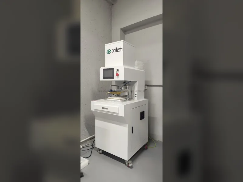
| OEL-CCD2400 | Offline, semi-automatic, before or after laminating | 6 × 4 MP (24 MP total), exposure 1-60 s | Up to 2600 × 1500 mm |
| OEL-S2400 | Offline, semi-automatic, before or after laminating | 2 cameras, 6000 × 4000, exposure 1-60 s | Up to 2500 × 1400 mm |
| OPT-S110H | String level, before layup | Cell string inspection | String, not module |
5. What EL Can and Cannot Prove About a Trail
Electroluminescence imaging is the most informative single method for deciding whether a visible trail coincides with a crack and whether an electrically inactive region is present. It is also the method most often over-trusted.
An EL image is not a photograph with an automatic pass or fail. Applied forward current, camera sensitivity, exposure, focus, ambient light, module temperature and image normalisation all change how the image looks. IEC TS 60904-13 specifies how EL images should be captured and processed, and gives guidance for qualitative interpretation. A dark region may indicate a crack, an interconnection defect, shunting or a finger interruption. Reading it correctly means putting the EL image next to the visual image, the module design and the I-V data.
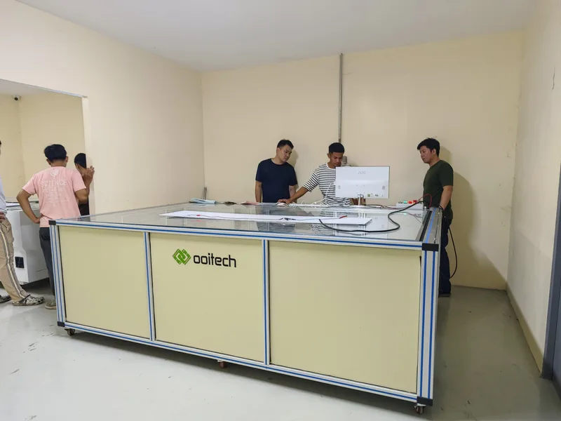
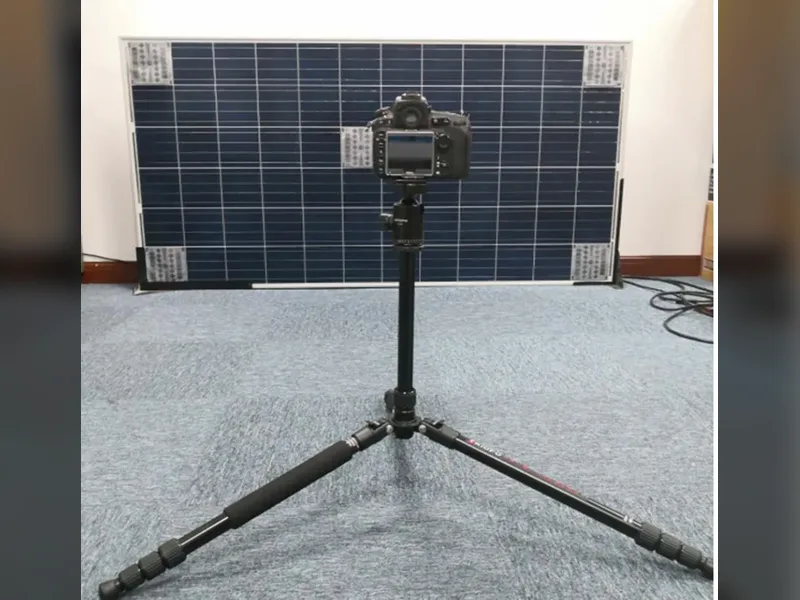
Fig. 3: An offline EL station with a glass stage. Because the module is loaded by hand, the station is not bound by line takt time, which makes it the practical place to re-inspect a suspect module or a returned unit.
| Method | What it establishes | Main limitation |
|---|---|---|
| Visual inspection | Documents the trail, delamination, bubbles, backsheet condition and burn marks | Cannot show whether a crack has isolated active cell area |
| EL imaging | Shows cracks, inactive regions and finger interruptions | Appearance depends on current, equipment, exposure and processing |
| I-V measurement | Quantifies power, current, voltage, fill factor and curve-shape change | Needs reliable irradiance and temperature data plus a valid comparison basis |
| Infrared thermography | Locates abnormal cell, substring, diode, cable or junction-box temperatures | Does not reveal crack geometry or the chemical cause |
| UV fluorescence | Reveals polymer aging and photobleaching patterns around cracks and cell edges | Not a quantitative moisture measurement and does not prove a reaction pathway |
| Laboratory analysis | Identifies silver compounds, corrosion products and polymer composition | May be destructive and costly; unsuitable for plant-wide screening |
Two limits are worth stating plainly, because they decide what you can promise a customer. EL imaging cannot see behind the aluminium frame or under the junction box, so anything in those areas has to be checked before framing. And EL imaging says nothing about the chemistry of a trail; it shows the electrical consequence, not the reaction that caused the discolouration.
When the question shifts from "is there a crack" to "what did it cost us in power", EL is no longer the right instrument on its own. I-V measurement supplies that number, and the two results should be compared per module barcode so that one module's electrical data and one module's image stay linked. The measurement procedure is set out in how to accurately measure the I-V curve of a solar PV module, and the station layout decisions are covered in EL testing for solar panels: inline vs offline setup.
6. Reducing Snail-Trail Risk in Materials and Process
If you cannot remove every crack, the next lever is the chemistry. That is where the encapsulant and backsheet choice enters the discussion, and where several common claims need qualifying.

Fig. 4: Encapsulant film. The film is the layer the silver grid actually sits against, so its formulation and additives determine which reactive species are available near the metallization.
In EVA-based modules, degradation can generate acetic acid, and acetic acid is one of the species implicated in silver-containing reaction products. Moving to a polyolefin-based encapsulant can remove the EVA deacetylation route to acetic acid. It is not a universal guarantee against discolouration: adhesion, additives, lamination conditions, optical stability, electrical properties and long-term interface compatibility still have to be evaluated as a complete material system.
The encapsulant comparison published on this site lists the parameters that are relevant to this decision, and they are worth reading as a set.
| Parameter | Value across the film range | Why it matters for a trail |
|---|---|---|
| Water vapour transmission rate | From 5-10 g/m²/day up to 30-40 g/m²/day (ASTM F1249), with polyolefin-based films at the low end | Governs moisture reaching the cell and metallization, though it is not the controlling factor identified for silver-acetate formation |
| Acid-free composition | Stated for the polyolefin films in the comparison | Removes the EVA deacetylation route that produces acetic acid |
| Anti-PID performance | Quoted per film type against IEC TS 62804 | Separates the PID clause from the snail-trail discussion, which are different failure modes |
| Processing temperature | 145-155 °C across the compared films (DSC analysis) | Sets the lamination window, and a mismatched window drives delamination and adhesion problems of its own |
| Peel strength to glass | Above 90 to above 120 N/cm depending on film (ISO 11339) | Adhesion failure opens the interfaces where transport and corrosion begin |
Backsheet selection deserves the same treatment, and here the evidence is easy to miss. Work on polymer foil additives has shown that additives in the foil itself can trigger snail-trail formation, which means two backsheets with similar datasheet permeability can behave differently in the field. Reviewing only the headline barrier number is not enough. The full comparison of film types, including the acid-free and anti-PID columns, is set out in our guide to EVA, POE and EPE encapsulant film for solar panel manufacturing.
Lamination sits between the material choice and the crack. A crack present at lay-up is carried into the finished laminate, and an out-of-window lamination process adds its own defects, including bubbles, delamination and frame jumping. Those are separate failure modes with separate causes, and they are covered in how to choose the right solar module laminator and in the real causes behind solar module bubbles.
7. FAQ
Do snail trails reduce solar panel power output?
The visible discolouration itself has no demonstrated direct influence on module performance. The risk comes from what the trail is following. If the underlying crack separates an active region of the cell, interrupts grid fingers, or creates current mismatch inside a substring, output can drop. A frequently cited study compared modules with visible trails against clean reference modules. Four selected modules produced roughly 68% to 88% of reference energy output. The authors attributed that shortfall to microcracks and damaged cell regions rather than to the discolouration. Those four modules were not a random sample, so the range should not be treated as typical. The only reliable answer for a specific module is an I-V measurement against a baseline.
What actually causes snail trails?
An interaction, not one cause. Published work points to three overlapping conditions: a pathway such as a microcrack or a cell edge, a chemistry involving the silver metallization and reactive species, and transport of oxygen and volatile products through the polymer layers. UV and temperature drive the reaction. Different silver compounds have been identified on affected modules, including silver acetate, silver carbonate, silver phosphate and silver sulfide, which suggests more than one chemical route produces a similar appearance.
Is moisture ingress the cause?
Not on its own, and this is where the popular explanation oversimplifies. In the modelling and accelerated tests that identified silver acetate, oxygen transmission through the backsheet had an important influence on formation, while water-vapour transmission was not found to control it within the range examined. Humidity still matters for corrosion, encapsulant degradation and delamination. But if a supplier answers your snail-trail concern with a water-vapour transmission figure only, the answer is incomplete.
How soon after installation do snail trails appear?
IEA PVPS reports that a snail track typically becomes visible at roughly three months to one year after installation. The timing depends on module design and the operating environment. That delay is the reason appearance-based acceptance clauses cause disputes: the condition often develops well after the modules have left the factory gate.
Are snail trails the same as PID?
No. PID is driven by system voltage combined with humidity and temperature, causing ion migration and shunting, and it is evaluated with damp-heat and voltage-stress testing under IEC TS 62804. A snail trail is associated with a physical pathway plus silver metallization chemistry. A module can have one without the other. Treat them as two clauses in the specification, not one.
Will switching from EVA to POE prevent snail trails?
It removes one route, because polyolefin encapsulants do not generate acetic acid the way EVA can. It is not a guarantee. Adhesion, additives, lamination conditions, optical stability and long-term compatibility with the adjacent layers also influence whether discolouration appears. Evaluate the laminate as a system, and note that additives in the backsheet foil have themselves been shown to trigger trail formation.
Can snail trails be removed or repaired?
No. The discolouration is a change in the metallization and in the encapsulant above it, and it is inside the sealed laminate. Cleaning the glass does not affect it. This is why prevention and earlier detection are the only practical levers, and why the useful intervention point is the crack on your line, long before any trail appears.
Should I reject a shipment because of snail trails?
Not on appearance alone, and not without evidence. Ask for an EL image of the affected module and an I-V curve against the factory flash data. The decision should rest on whether an electrically inactive region, a broken grid finger or an interconnect fault is present. A trail that coincides with no electrical abnormality is a cosmetic finding; one that coincides with a separated cell region is a performance and warranty finding.
How do I detect the crack that a trail will follow?
With EL imaging at more than one production stage. A single station at the end of the line confirms that a crack exists but cannot tell you whether the stringer, the lay-up step or the framing press introduced it. A string-level inspection before layup plus a module-level inspection after lamination localises the stage, which is what allows you to fix the process at its source.
Final Thoughts
Treat snail trails as two questions, not one. The trail is a materials and chemistry outcome that you influence through the encapsulant and backsheet system. The crack that the trail follows is a process outcome that you influence on the line, and it is the one that carries the electrical risk. Decide your acceptance criteria in terms of EL images and I-V data at named production stages, then ask for oxygen transmission rate alongside water-vapour transmission rate when you qualify the laminate. If you tell us your module size, cell technology and where you want inspection to sit, we will propose the EL configuration and the specific inspection stages.