Martin Green's Team: Stop Falling for the 'Perovskite in Space' Hype — 20% Loss After Just 100 Cycles
Table of Contents
Introduction
A surprising fact: the biggest obstacle to the perovskite "space dream" isn't cosmic radiation — it's the temperature swing of dozens of degrees a satellite endures as it circles Earth 15 times a day. Roughly the same swing crystalline silicon modules face in a TC test.
A few days ago a friend who works on satellite power systems asked me: "You PV folks keep talking about how efficient perovskite is. Can it be used on small satellites? It's light, high power density."
I said: "Don't rush to look at efficiency. Do you know how many thermal shocks a satellite goes through in a single day on orbit?"
He said: "Isn't it just hot during the day and cold at night?"
"Yes, but do you know how fast it heats from -80°C to +80°C?"
He thought about it: "A few degrees a minute?"
"Measured data: 6.77°C per minute. Some labs, to simulate the space environment, push it straight to 16°C per minute."
He paused: "Can perovskite handle that?"
"It can't. There's a brand new paper in a Nature sister journal studying exactly this."
This paper (Energy & Environmental Science, DOI:10.1039/d5ee03704b) is a collaboration between UNSW, Korea's KRICT, and the UK's University of Surrey. They used real satellite data to define a test standard, then threw perovskite into a -80°C to +80°C thermal shock chamber for 100 cycles to see what survives.
Let me break this down in plain PV language.
The Thermal Shock in Space Is Far Harsher Than You Think
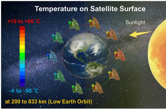
In Low Earth Orbit (LEO, altitude 200-2000 km), a satellite circles Earth about 15 times a day. Each orbit goes through a switch from sunlight to Earth's shadow and back to sunlight.
How fast is this process?
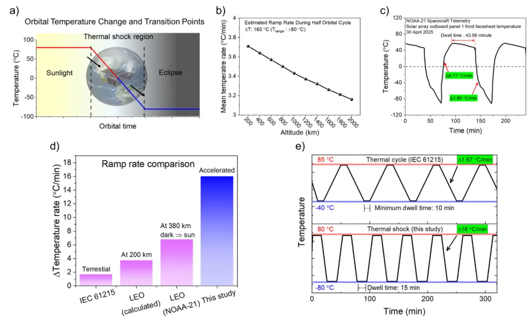

Look at Figure 2c: measured data from the NOAA-21 satellite — going from shadow into sunlight, the heating rate is 6.77°C/min. Going from sunlight into shadow, the cooling rate is gentler, about 1.89°C/min (because heat is dissipated by radiation, which is slower).
This rate is 4 times faster than the 1.67°C/min required by the ground-level IEC 61215 standard.
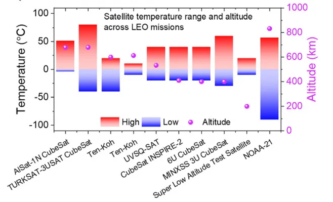
The satellite surface temperature range is measured at -90°C to +80°C (Figure 1b). The ECSS (European Cooperation for Space Standardization) qualification range is even wider: -175°C to +125°C.
So this paper defined the following accelerated test condition (Figure 2d):
Temperature range: -80°C ↔ +80°C
Ramp rate: 16°C/min
Number of cycles: 100
16°C/min is 2.4 times the NOAA-21 measured rate. This is no longer "simulation" — it's accelerated aging, using harsher conditions to rapidly expose the material's weaknesses.
What Happens to Perovskite Under Thermal Shock
The material they used is FAPbI₃, one of the highest-efficiency single-junction perovskite systems available (lab efficiency >27%). But FAPbI₃ has a fatal weakness: it is metastable at room temperature and easily transforms from the α phase (black, highly active) to the δ phase (yellow, inactive).
To stabilize the α phase, a bit of MAPbBr₃ is usually added. The paper tested five concentrations: 0%, 1%, 3%, 5%, and 7%.
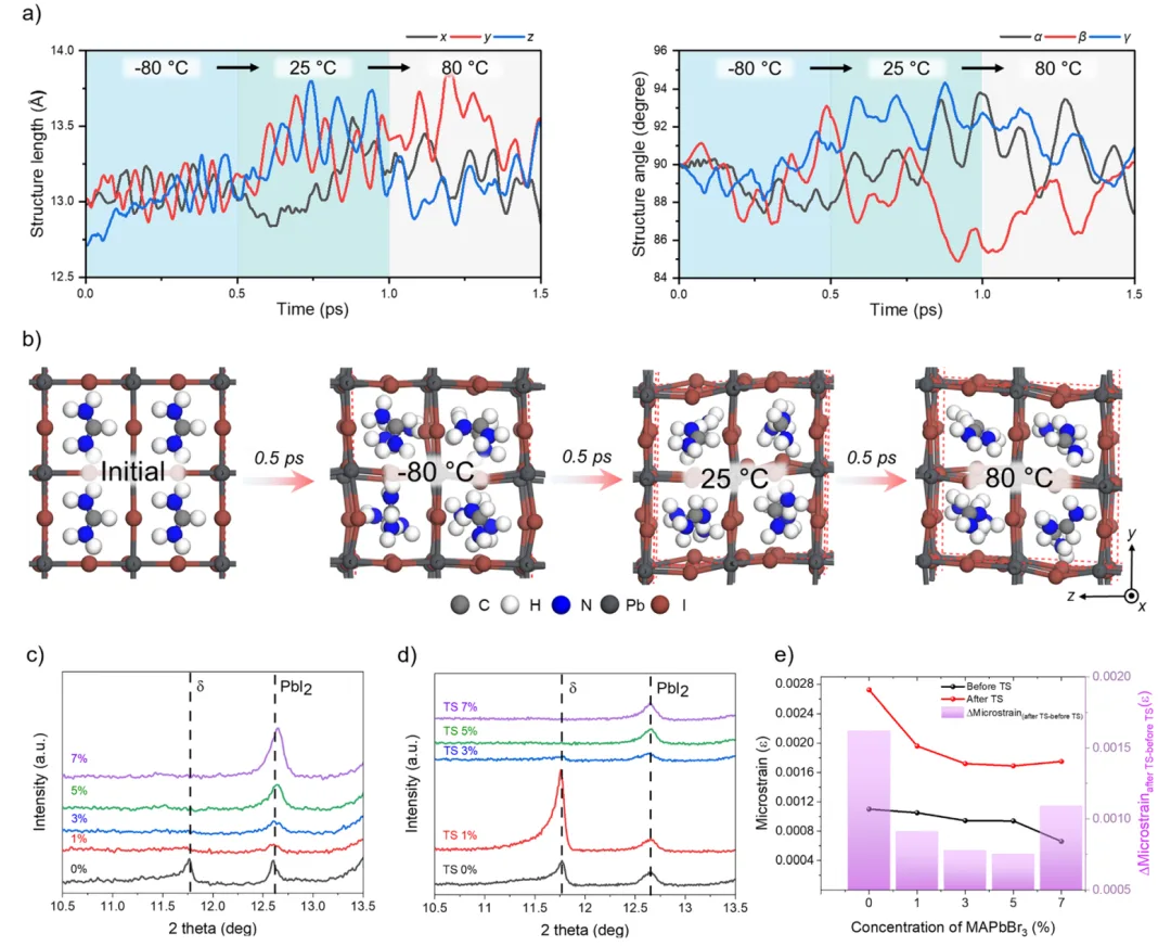

Look at the molecular dynamics simulation (Figure 3a): heating FAPbI₃ from -80°C to 80°C, the lattice constant grows, the PbI₆ octahedra start to tilt, and FA ion displacement intensifies — the structure is "trembling."
Now look at the XRD after 100 thermal shock cycles (Figure 3c-d):
| MAPbBr₃ concentration | 0% | 1% | 3% | 5% | 7% |
|---|---|---|---|---|---|
| Change after thermal shock | Large amount of δ phase appears | Stable | Stable | Stable | PbI₂ increases |
Conclusion: adding a little (1-5%) stabilizes the α phase, but adding too much (7%) precipitates PbI₂, which is actually worse.
Now look at KPFM (Kelvin Probe Force Microscopy) measuring surface potential (Figure 4):
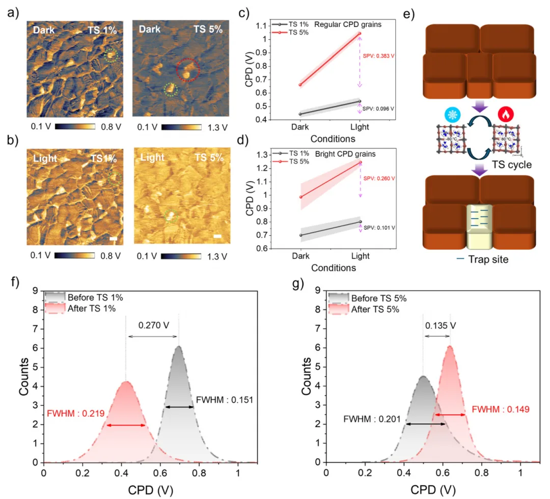

1% sample: after thermal shock, the potential difference between grains increases, indicating grain boundaries become recombination centers
5% sample: after thermal shock, the potential distribution is more uniform and the damage is smaller
The paper uses SPV (Surface Photovoltage) to quantify this — the higher the SPV, the better photogenerated carriers are separated. The 5% sample's SPV is about 1.5 times that of the 1% sample.
Made Into Cells, How Much Is Left
They built a full cell structure: ITO/SnO₂/perovskite/PEAI/PTAA/Au, vacuum-encapsulated and tossed into the thermal shock chamber.
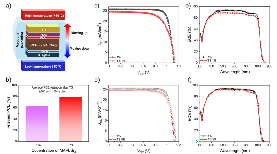

Results (Figure 5b):
| MAPbBr₃ concentration | 1% | 5% |
|---|---|---|
| Efficiency retention after thermal shock | ~62% | ~80% |
The 5% sample, after surviving 100 cycles of -80°C ↔ +80°C thermal shock, still retained about 80% of its efficiency.
Look at the J-V curves (Figure 5c-d):
1% sample: Jsc and FF drop badly
5% sample: curve shape is much better preserved
EQE (Figure 5e-f) confirms it: the 1% sample drops across the whole band, while the 5% sample only declines slightly in the long-wavelength region (700-800nm) — possibly due to interface thermal expansion mismatch.
How Does It Perform at 35 km Altitude
After the lab tests, they needed something real. Partnering with the University of Pisa in Italy, they sent the cells up to 35 km altitude on a high-altitude balloon (Figure 6a).
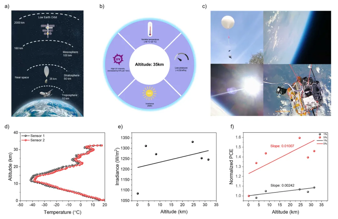

At this altitude, atmospheric pressure is only 2% of ground level, air density is 1.5%, temperature can reach -40°C, and the cells face near-space UV radiation and the AM0 spectrum.
Results (Figure 6f):
1% sample: PCE slowly declines as altitude rises
5% sample: PCE actually rises as altitude increases
Why does the 5% sample perform better at high altitude? As altitude rises, irradiance increases and Jsc should increase linearly. But the 1% sample's Jsc increase slope is only 0.00016, while the 5% sample's is 0.00364 — a difference of an order of magnitude.
This shows the 1% sample suffers severe non-radiative recombination — photogenerated carriers are swallowed by grain boundary defects before they even emerge. The KPFM SPV data already foreshadowed this result.
Takeaways for Production Line Engineers
Don't just look at efficiency — look at how much it can endure
This paper offers a solid testing framework: use 16°C/min rapid thermal shock for accelerated aging, then use a high-altitude balloon for near-space validation.
We don't build satellites, but this approach transfers — when evaluating new materials and new processes, consider using faster temperature ramp rates for "stress testing" to expose interface and grain boundary issues early.
Stabilization methods may bring new problems
Adding MAPbBr₃ to FAPbI₃ does stabilize the α phase. But adding too much (7%) causes PbI₂ to precipitate and makes things worse.
This is the same logic as encapsulant film selection — there's no universal recipe, only a "balance point." When selecting, you can't just look at "whether it's there" — you have to look at "how much."
Lab data and high-altitude data line up
The most solid part of this paper is that the SPV difference measured by KPFM can predict the Jsc slope difference, and the EQE drop in long wavelengths corresponds to interface thermal expansion mismatch.
Good failure analysis should let you use lab tools to predict field performance in advance.
Crystalline silicon's stability is its greatest moat
Look at this paper's test conditions: -80°C to +80°C, 100 cycles, 16°C/min.
This still doesn't reach the ECSS standard, but it's already routine for crystalline silicon. In the TC200 (200 thermal cycles) test from -40°C to +85°C, crystalline silicon fails if degradation exceeds 2%.
For perovskite to replace crystalline silicon, it's not enough to catch up on efficiency — it has to survive 25 years under the same test standards.
Interactive Poll
Do you believe in perovskite going to space?
Leave your thoughts in the comments.
Reference Information
Title: Towards space compatible perovskite solar cells: guidelines for thermal shock resilience and near space balloon testing
Year: 2026
DOI: 10.1039/d5ee03704b
Ooitech's View
Ooitech believes: perovskite's path to space hinges not on chasing efficiency, but on surviving brutal thermal shock cycling — and that endurance, not raw efficiency, is the real measure of a solar cell's worth.