How Silver Paste "Bites Through" poly-Si on the TOPCon Rear Side
Table of Contents
Introduction
Last time we talked about front-side silver paste. The whole point there was "burn it through." Why can one laser process force the entire front-side silver paste to be replaced?
The rear side is exactly the opposite.
Silver still has to go in. But once it's in, it has to stop right away.
Because on the front, if silver doesn't burn in, contact resistance won't come down. On the rear, if silver burns too deep, it punches straight through the most valuable part of TOPCon — the passivated contact.
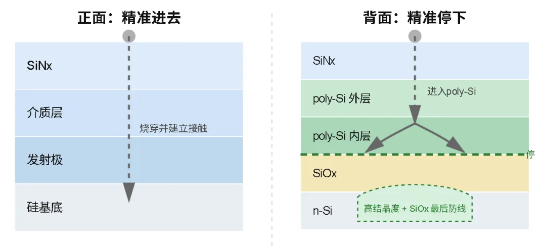
So front-side metallization is about "how to get in." Rear-side metallization is about "how to stop once you're in."
This piece breaks the rear side down all the way: why silver "bites through" poly-Si, what happens once it does, and how the latest bilayer poly-Si design builds silver a road that says "stop on arrival."
Look at the Rear-Side Layout First
What the rear stack actually looks like
From the outside in, the TOPCon rear is stacked roughly like this: SiNx protective layer, (some makers run dual-side ALD and add an AlOx layer on the rear too), poly-Si, tunnel oxide, and underneath that sits the n-type silicon substrate.
The biggest difference from the front is that bottom layer — the tunnel oxide, only about 1–1.5 nm thick. It's the lifeline of the whole rear-side passivation. The entire passivation value of poly-Si rides on this film staying intact.
The job boundary of rear silver paste is different from the front too. Burning through the SiNx protective layer can't be skipped — that's the entry ticket, same as the front. But its contact target lives inside the poly-Si. Poly-Si is heavily doped, it's a conductive layer by itself. Once silver reaches the poly-Si and forms contact, the job is done.
Then it has to stop.
If silver keeps going down, through the tunnel oxide and into the silicon substrate — the passivated contact is dead on the spot. Recombination centers show up across the interface, Voc drops, and the foundation of this cell is ruined.
A production-line side note: that rear AlOx layer is still optional right now, and plenty of makers skip it. But as rear poly finger and other localized structures develop, the passivation demand in non-metallized regions will keep climbing, and dielectric passivation layers like AlOx will clearly matter more. So a film layer that looks "optional" today may actually be reserving an interface for the next-gen localized poly-Si structure. Read that evolution, and you see the rear film design is paving the road for the next step.
Single-Layer poly-Si — Why It Can't Hold the Line
First, how silver "bites" its way in.
The front-side piece covered it: during firing, silver dissolves into the molten glass phase and migrates along with the glass. On the rear, this same mechanism keeps running — the difference is that the front-side emitter welcomes silver spikes stabbing in, while the rear poly-Si can't tolerate silver going any deeper.
The problem with single-layer poly-Si is structural: it's built up from grains, and the grain boundaries run all the way top to bottom. Grain boundaries are a key fast channel for silver to migrate into the depths of poly-Si.
Once silver migrates down along the grain boundaries and reaches near the tunnel oxide, it can further trigger local damage or form a metal penetration path, finally carrying silver into the silicon substrate — and from that moment, the physical basis of the passivated contact is gone.

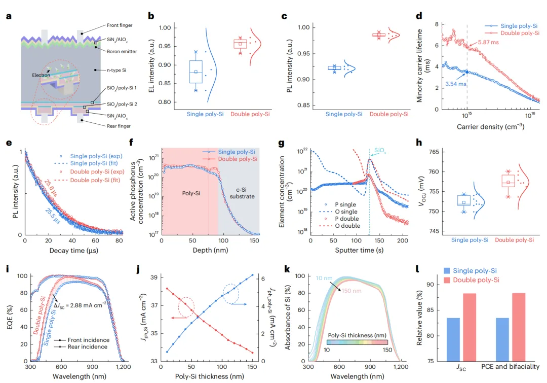
This isn't speculation, it's a documented observation. In the 26.66% paper published in Nature Energy by Ningbo Institute of Materials and JinkoSolar, HAADF and HR-TEM gave the firing interface of a single-layer poly-Si sample a full physical exam: silver nanoparticles appeared scattered inside the silicon substrate, with silver traces running all the way from poly-Si into the substrate. The tunnel oxide itself was still intact, but it didn't hold the silver back — a single barrier can't stop the silver pouring down along the grain boundaries.
Bilayer Design: Not Blocking It Dead, but Leaving a Door
The counter-intuitive part of the paper's solution: instead of blocking silver dead, they built silver a road that says "stop on arrival."
The rear was made with two poly-Si layers, about 100 nm total, each doing its own job. This describes the specific bilayer structure used in the paper. Not every bilayer poly-Si follows this fixed 60/40 nm, heavy-doped/light-doped configuration.
Outer layer, 60 nm, heavily doped, mostly amorphous — the reception hall. Lots of grain boundaries, high phosphorus concentration, silver walks in freely. Once it reaches position, it forms an ohmic contact with the heavily doped poly-Si. This is the "conduct" role: contact must form, current must come out.
Inner layer, 40 nm, lightly doped, highly crystalline — the gate. High crystallinity, low grain boundary density, silver has nowhere to go once it gets here. This is the structural layer doing the "blocking."
Tunnel oxide — the last chemical barrier. It's not just physically thin. More importantly, it changes the interface conditions for silver to keep migrating toward the silicon substrate and to form a stable metal phase. When silver is stopped near the highly crystalline poly-Si and the SiOx interface, forming a metal penetration path down to the substrate becomes much harder.
So the real "brake" isn't done by any single layer alone. It's the highly crystalline poly-Si + tunnel oxide together that make up the final line of defense.

The HR-TEM comparison makes it vivid: in the single-layer sample, silver penetrates into the substrate as scattered dots. In the bilayer sample, after silver has punched through most of the outer layer, it gets forced by the inner layer into a "bowl shape" — it spreads sideways but can't go down anymore.
The effect is direct too: implied open-circuit voltage went from 752 mV up to 757 mV. Behind that 5 mV gain is one core fact — silver penetration was clearly suppressed, and the passivation was preserved. This 5 mV wasn't "made," it was saved — voltage that would otherwise have been lost.
One line to sum up this design: the wisdom of blocking silver isn't in "plugging," it's in "layering" — the greeters greet, the gatekeepers keep the gate. The outer layer handles making contact, the inner layer holds the bottom line, and the tunnel oxide backs up the last stop.
Payoff, Cost, and Where It Sits in the Industry
First the payoff: Voc,i +5 mV. The rear-side pillar of that 26.66% certified efficiency is exactly this bilayer structure.
Now the cost, straight up: one more deposition, one more interface. The added process complexity and cost are real. And the paper itself admits the outer layer didn't stop 100% of the silver — that last gate relies on the combination of inner-layer poly-Si plus the tunnel oxide.
On the industry map, this isn't a one-off. JinkoSolar's earlier certified 26.35% bifacial TOPCon used exactly a bilayer SiOx/poly-Si structure plus UV picosecond laser selective modification. And more than one academic team is working on Bilayered and Triple-layer poly-Si. Functional layering of poly-Si is the direction the industry is heading — behind it is the same logic: peel the two jobs of "contact" and "passivation" off a single film, and hand each to its own layer.
Worth drawing a distinction here: even with the same bilayer poly-Si, the two recent records use it differently. In the Jinko 26.35% paper (Yangzhou University + Jinko, EES), the bilayer structure paired UV picosecond laser modification with wet etching to selectively thin the outer poly-Si in the rear non-metallized region — the goal was to cut parasitic absorption and lift bifaciality. That's an "optics problem." The Ningbo 26.66% paper aims the bilayer structure at blocking silver and preserving passivation. That's an "electrical problem." Bilayer poly-Si is like a platform — different teams solve different problems on it, but the direction is the same: let each layer do just one thing. In Ye Jichun's team's own list of the next-stage efficiency levers for TOPCon, bilayer poly-Si structures and localized polysilicon (poly finger) sit right up front — this Nature Energy paper just turned the first item on that list into a record.
Still have to throw some cold water: these records were all made on lab equipment, the papers say so themselves. From lab to mass-production line, yield, cycle time, cost — every gate has to be cleared again.
One Table to Make It Clear
| Item | Front Side | Rear Side |
|---|---|---|
| Metal faces | Multiple dielectric films + emitter | SiNx + poly-Si + SiOx |
| Biggest problem | Silver won't burn in | Silver burns too deep |
| Traditional fix | Add aluminum to boost contact | Single-layer poly-Si direct contact |
| New problem | Aluminum harms passivation | Silver penetrates poly-Si |
| New solution | LECO + aluminum-free silver paste | Bilayer poly-Si |
| Core idea | Burn in precisely | Stop precisely |
Three Lines to Take Back to the Line Crew
First, the rear-side disease and the front-side disease show up on two different parameters. When the front goes wrong, it usually shows in FF (contact resistance). When the rear goes wrong, it usually shows in Voc (passivation punched through). When you're chasing a Voc anomaly, besides checking the passivation process, firing temperature and poly-Si structure should both be on the list.
Second, how far silver travels is decided by structure. Firing only controls the throttle. How deep silver goes — the upstream is the poly-Si structure design: single or bilayer, high or low crystallinity, doping concentration gradient. The firing window only controls the speed on that track. If the structure doesn't provide a line of defense, no amount of fine firing tuning will save it.
Third, layering is the trend. Watch the supporting stack closely. Functional layering of poly-Si, rear poly finger, AlOx going from optional to mandatory — these evolutions are all tied together. When you plan a process, don't just look at a single step, look at the direction the structure is evolving.
So the real efficiency lever in TOPCon metallization isn't burning the silver "harder," it's knowing where the silver should end up.
Front side: let it get in precisely. Rear side: let it stop precisely.
And the next step forward is making the silver itself less and less.
Ooitech's View
The part that always bites us on the shop floor is that Voc problems rarely trace back to a single knob. A rear Voc that won't recover no matter how you tune the firing window is usually a structure story, not a paste story — and bilayer poly-Si is basically the industry admitting that. Worth remembering these numbers still come off lab tools, so the leap to a real line is where yield and cycle time do the talking. If you like this kind of cell-level teardown, the YouTube channel at www.youtube.com/ooitech has more from inside real module lines.