Solar Module Stringing: A Practical Guide
Table of Contents
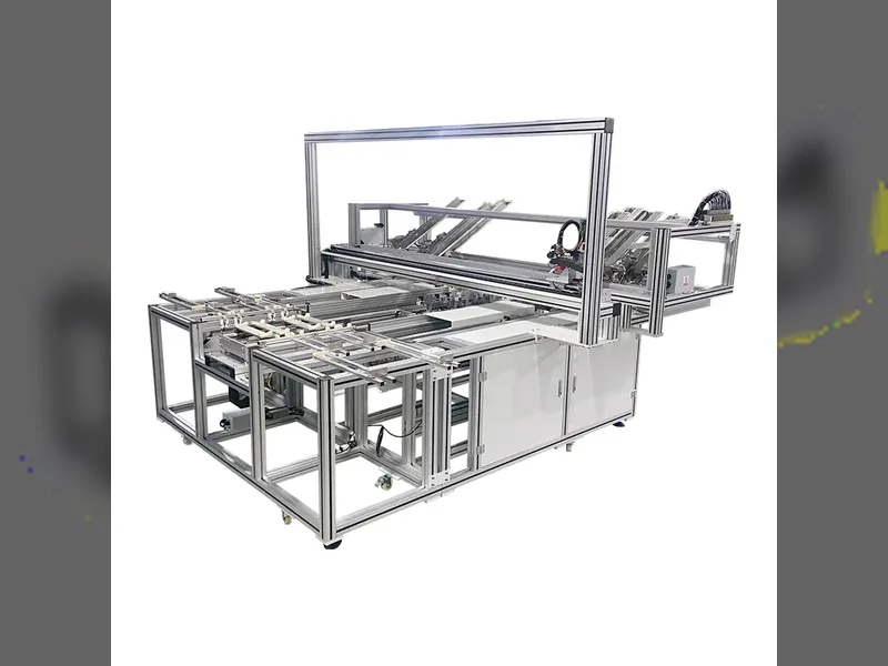
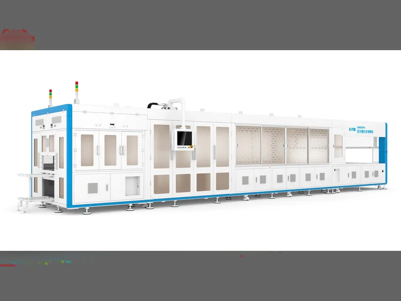
Quick answer: Stringing is the step where individual solar cells are soldered into a series string, and it sets both the module's power and the ceiling on line yield. A tabber places and solders ribbon onto each cell; a stringer then lays those cells in sequence and joins them. Because a cracked cell or a cold solder joint cannot be repaired downstream, everything that goes wrong here is written into the finished module. Practical stringing work comes down to four variables: cell format flexibility, busbar count for multi-busbar layouts, ribbon placement accuracy, and breakage rate. Ribbon thickness matters too — thinner ribbon lowers material cost and raises resistance, so there is a floor below which the efficiency gained at the cell is lost again at the joint. Machine platforms such as the ATW050 class handle multiple cell formats without a line change.
PV Module Manufacturing · by Jerry, Ooitech
Product Introduction
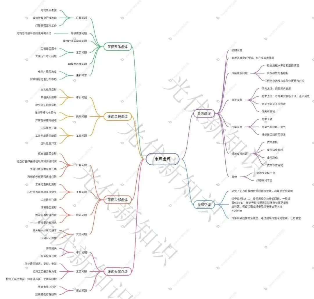
No long intro. The mind map goes first. If it helps, save the article and download the image. You can also reach out through the WeChat backend to join the PV module tech chat group for the high-res version. (Just tell us which part you handle, like process, quality, equipment, or production.)
Before we get into cold solder troubleshooting, let's walk through how stringing actually works. The ribbon, pulled by the drawing mechanism, is placed precisely right above the busbar of the cell. Then the welding fixture comes down, and the press pins on the fixture apply pressure to the ribbon so it touches the busbar. The cell moves under the light box of the stringer, where infrared heats the ribbon and the cell. The tin on the ribbon melts and bonds with the silver paste on the busbar, forming a metal alloy.
One thing to keep in mind. For any cold solder inspection, check for exposed white (unbonded) areas first. If you see exposed white, deal with that before you judge the soldering itself. Everything below uses TOPCon cell stringing and the ATW050 stringer as the example.
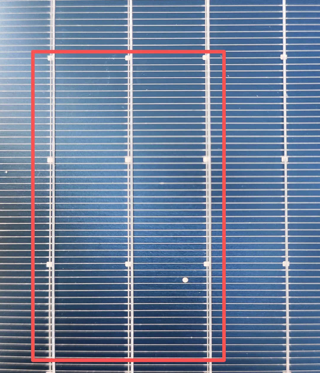
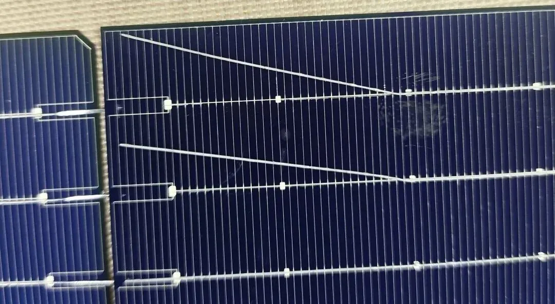
As shown, the first, second and third ribbons inside the red box are exposed white. The fourth one outside the box is normal.
Technical Parameters
1. Front full-panel cold solder
When the whole front side shows cold solder, check these:
| Item | What to look at |
|---|---|
| Light box | Focus on the soldering parameters. Is the light box aging? Look at anything that affects the whole panel's heating. |
| Welding height | On stop, the light box lifts a bit to avoid over-soldering the cell underneath. If the gap between the light box and the welding platform is too big during soldering, infrared efficiency drops and you get cold solder. |
| Time and power | Soldering time and light box power are the big factors. Check these first. |
| Flux concentration | Abnormal flux, especially too low, fails to clean the oxide off the ribbon surface, and soldering quality drops into a full-panel cold solder. |
| Incoming material | Cells with too little silver paste cause cold or over solder. Uneven tin coating on the ribbon means the thin spots can't bond well with the paste. Expired or degraded flux won't remove oxides and the joint fails. |
| Fixture | Is the fixture centered? An off-center fixture means the press pins can't hold the ribbon against the busbar, leaving a gap and cold solder. Also check the press pins themselves. |
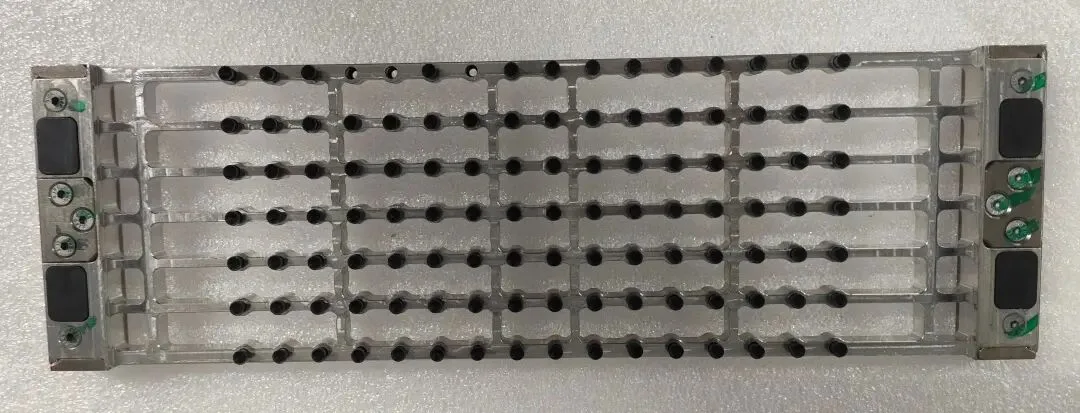
16BB welding fixture
2. Front single-ribbon cold solder
Since it's a single ribbon, just check the mechanism tied to that specific ribbon.
| Item | What to look at |
|---|---|
| Drawing | Loose draw clamp, damaged clamp, or bad clamp bearing. Any fault on that single ribbon's mechanism puts the ribbon out of position and hurts the joint. |
| Lifting | Foreign matter in the lifting guide slot, or the ribbon scraping inside the slot. |
| Fixture | Fixture normal? Fixture pad worn? Press pin abnormal? |
| Light tube | For cold solder at a fixed spot, check the light tube at that position for aging or wrong power. |
| Cutter | After cutting, does the ribbon have bends or burrs? Both make the ribbon scrape on the belt or other parts and ruin the joint. |
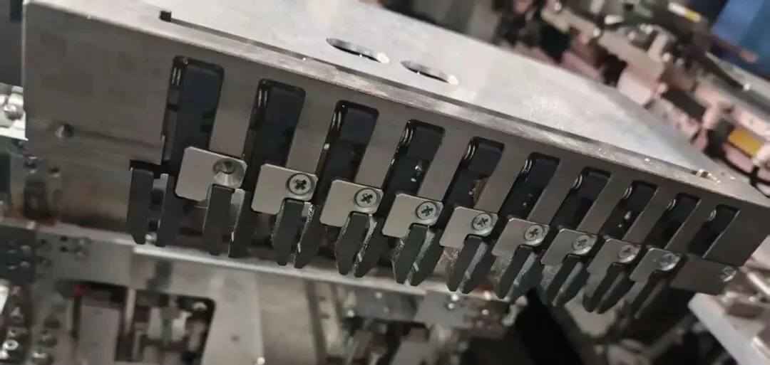
10BB stringer drawing mechanism
3. Front head cold solder
| Item | What to look at |
|---|---|
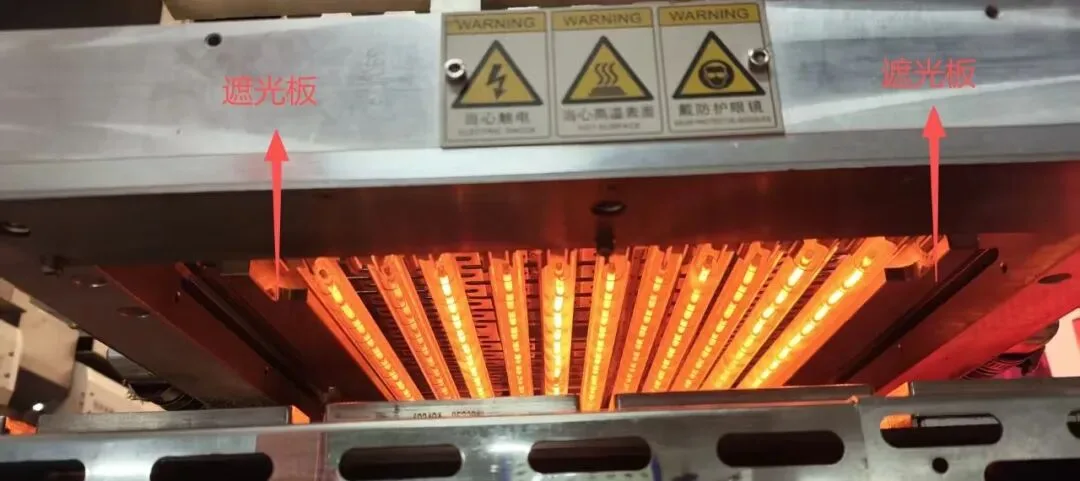
| Light box | Is the shading plate deformed or blocking the light tube? Wrong shading plate position lets the ribbon melt tin before it enters the light box, that is premature tin melting, and you get head cold solder. Check the standby power and soldering time of the light tube. |
| Fixture | Is the fixture arched or deformed? An arched fixture can't press the ribbon, so cold solder shows up. Do all press pins hold the solder head? Is the fixture slipping? |
| Ribbon | Deformed or over-stretched ribbon bends and can't line up with the busbar, causing cold solder. Also check for lifted ribbon ends, which can't touch the busbar. |
| Other | Was the moisture dried after cell cutting? |
4. Head and tail spot cold solder
| Item | What to look at |
|---|---|
| Drawing | Lifted ribbon end or over-stretched ribbon. |
| Fixture | Press pin fallen off, deformed, or stuck. Spot cold solder usually comes from a press pin problem. Without the pin, the ribbon can't reach the busbar. |
| Flattening | Flattening too close to the loading area, or flattening flipping over. |
5. Back-side cold solder
| Item | What to look at |
|---|---|
| Adsorption | When the base plate adsorption is off, the cell and ribbon shift relative to each other while moving, causing back cold solder. (Usually full back-side.) |
| Welding base plate | Poor base plate levelness or heavy wear. Is the base plate magnet lifted? Do the cell and base positions match? |
| Tail clamp | Tail clamp too low, stuck, unable to grip the ribbon, or foreign matter inside. |
| Lifting | Lifting stuck, cylinder damaged or leaking, or abnormal ribbon sealing, so the ribbon bounces and shifts and doesn't seat right. |
| Welding belt | Worn belt, lifted edges, or foreign matter under the belt shifts the back ribbon while the cell and fixture move. (Nothing else affects it. The front ribbon is held by the fixture and won't shift easily.) |
| Other | Bad incoming cells or bad incoming ribbon. |
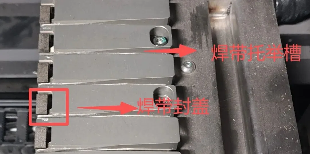
Guess how many BB this lifting jig is for. (PS: haven't used it in half a year.)
Technical Advantages
Logic-first troubleshooting: always check exposed white before judging the joint, so you fix the real defect not the symptom
Location-based method: front full-panel, single ribbon, head, tail spot and back side each have their own checklist, so you narrow down fast
Root-cause coverage: light box, drawing, lifting, fixture, ribbon, flux, base plate and belt are all mapped to specific defect types
Real-line reference: built around TOPCon cells and the ATW050 stringer, matching what operators actually see on the floor
Product Application
This troubleshooting logic applies across mainstream module lines. On the front side, the light box, fixture centering and flux concentration usually explain full-panel issues, while single-ribbon and head defects point back to the drawing and cutting mechanisms. On the back side, adsorption, base plate levelness and belt condition are the usual suspects. Whether you run a 10BB, 16BB or MBB stringer, the same defect-to-mechanism mapping keeps process, quality, equipment and production teams on the same page during a cold solder chase.
Ooitech's View
What we see on real lines matches this guide closely: most cold solder complaints trace back to fixture centering and flux state long before the light box itself is to blame, so checking exposed white first saves a lot of wasted teardown time. TOPCon busbars are thinner and the silver paste window is tight, which is exactly why ribbon flatness and press-pin condition matter more than they did in the PERC days. We tune these parameters during commissioning and operator training for every module line we deliver, and if you want to see stringing setups like the ATW-style flow in action, the Ooitech YouTube channel at www.youtube.com/ooitech has plenty of factory footage worth a look.
Note: the article references ATW's "Summary of Soldering Defects".